
Body frame of a riding tractor

Inactive Publication Date: 2005-08-30
KANZAKI KOKYUKOKI MFG
View PDF3 Cites 7 Cited by
  • Summary
  • Abstract
  • Description
  • Claims
  • Application Information

AI Technical Summary

Benefits of technology

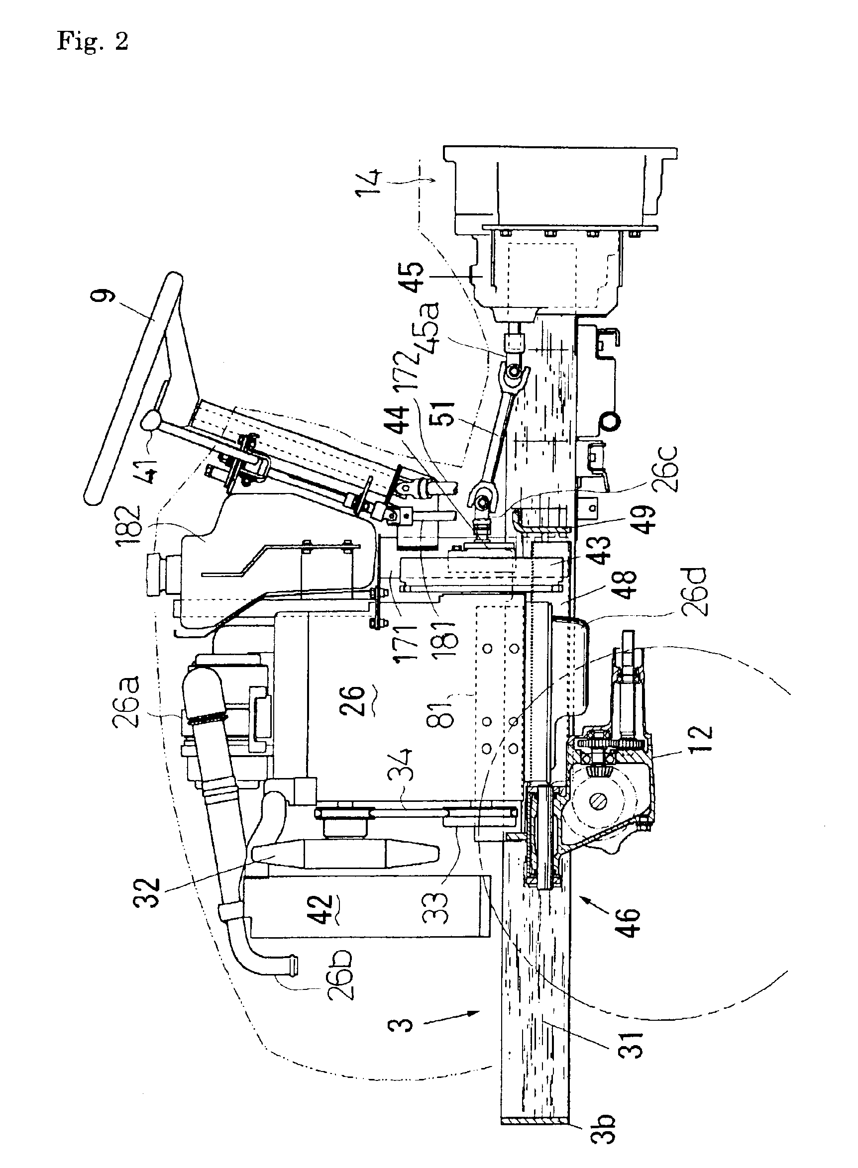
[0012]An object of the present invention is to provide a body frame of a riding tractor for mounting an engine thereon, an axis of the engine being oriented lengthwise along the tractor. A flywheel is provided on the axis of the engine, comprising a pair of left and right side members extended lengthwise along the tractor, cross members disposed in front and rear of the engine, respectively, so as to connect the left and right side members to each other, and a reinforcing member provided on an inside portion of each of the left and right side members. The body frame can be laterally narrowed and lightened while ensuring the rigidity thereof, thereby being applicable to a small tractor.
[0013]According to the present invention, each of the reinforcing members is disposed laterally inward from the laterally outermost end of the flywheel in a space between the engine and each of the left and right side members. Thus, the dead space between the engine and the side member is effectively utilized for arranging each of the reinforcing members even if the side members closely approach the engine so as to narrow the body frame for increasing the rigidity thereof. Consequently, the lateral width of the body frame can be reduced so as to be applicable to a small tractor having a laterally narrow body while the reinforcing members are prevented from interfering with the engine.
[0015]Preferably, a stay, on which a vibration proof member for anti-vibratory support of the engine is mounted, is provided on a side surface of each of the left and right side frames so as to extend laterally outward from each of the side members. Therefore, the reaction force of the engine is efficiently supported, and an influence of vibration of the engine onto the body frame is reduced, thereby realizing a weight saving in the body frame.
[0016]An axle casing may be suspended from one of the cross members. However, the lower portion of the engine between the side members can be disposed so as to lower the weight of the tractor body while the body frame is prevented from interfering with the axle casing.

Problems solved by technology

However, the above-mentioned conventional body frame is complicated in that the side members are disposed on the left and right outsides of the engine while being prevented from interfering with a front axle casing provided below the engine.
Moreover, equipping the reinforcing members on the body frame is difficult because the reinforcing members must be provided on the inside of the respective C-like shaped side members while a sufficient space for the lower portion of the engine must be secured between the right and left side members in consideration of vibration of the engine.
Hence, as the body frame must be designed so as to fulfill various requirements as mentioned above, the structure becomes complicated, which increases production costs and the body weight of the tractor.
In addition, this construction of the body frame is wide so as not to be suitable for a small tractor.

Method used


Image

  • Body frame of a riding tractor
  • Body frame of a riding tractor
  • Body frame of a riding tractor

Examples


Embodiment Construction

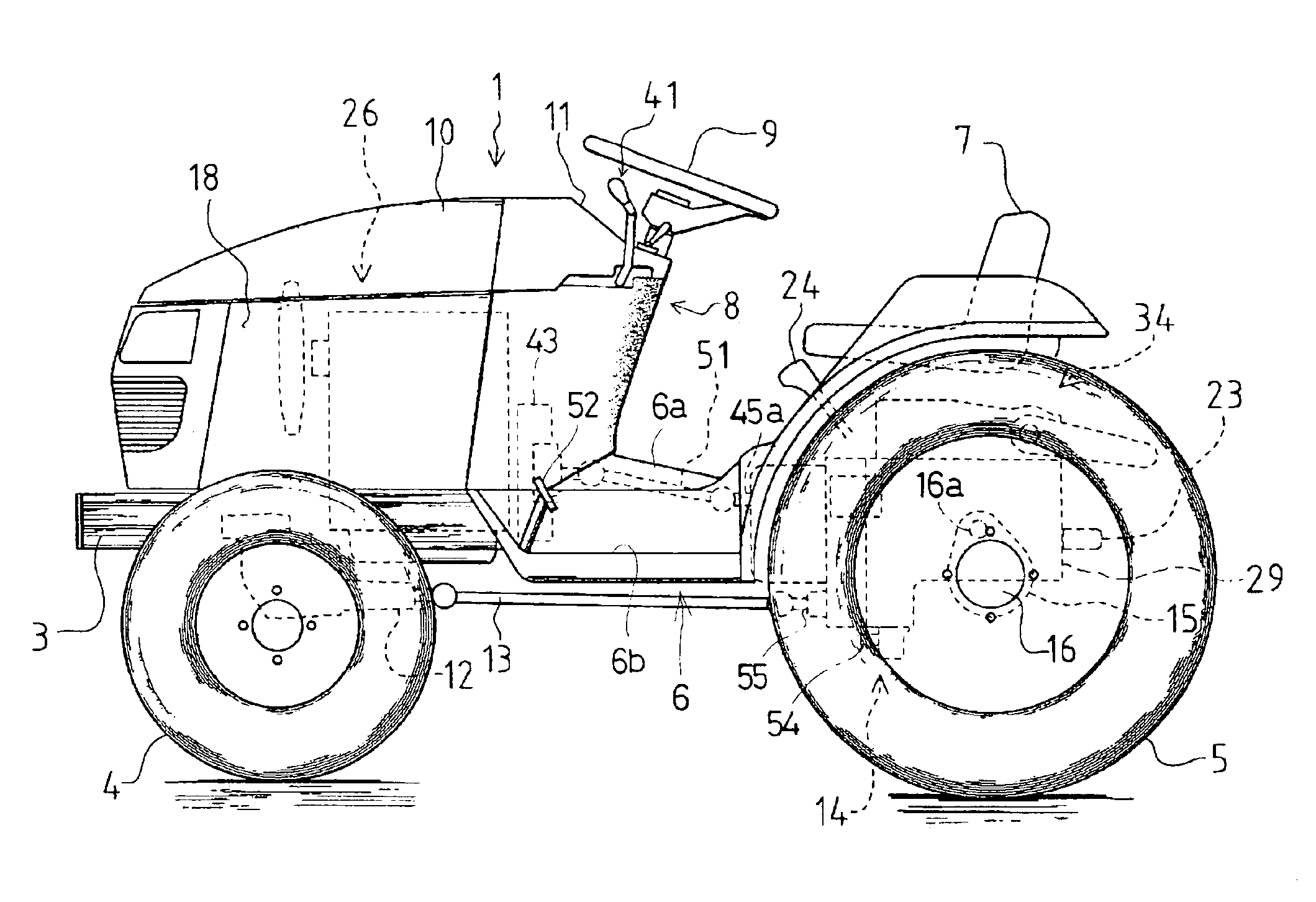
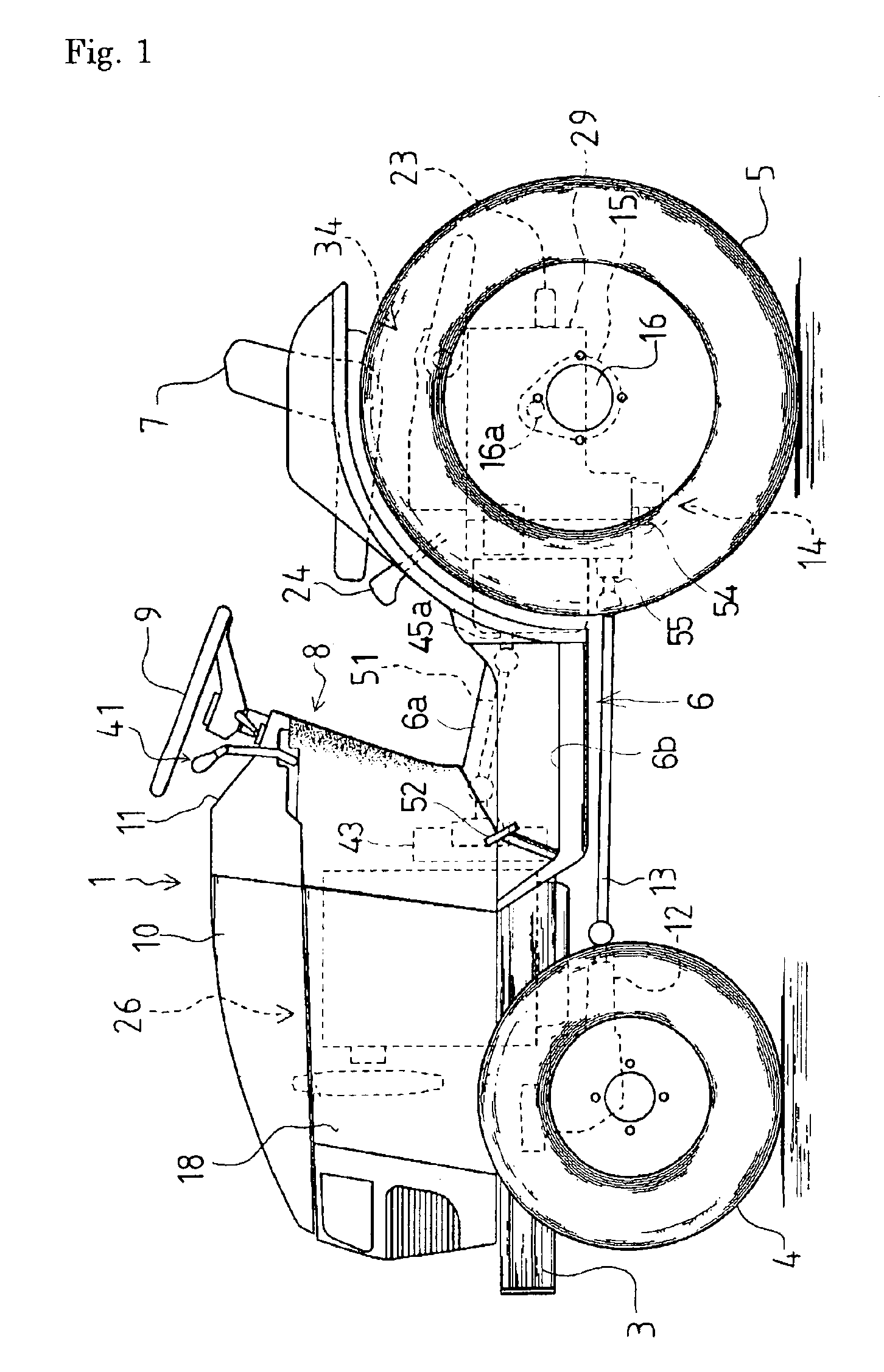
[0028]Referring to FIG. 1, description will be given of an agricultural tractor 1 according to an embodiment of the present invention. The agricultural tractor 1 has a body frame 3, whose rear end is attached to a front surface of a transmission casing 29 of a transmission 14. On left and right side surfaces of a rear portion of transmission casing 29 are disposed respective rear axle casings 15.

[0029]An engine 26 is mounted on body frame 3, and covered with a bonnet 10, left and right side covers 18, and any additional covers as desired. A dashboard 8 is vertically mounted on the longitudinally intermediate portion of body frame 3 and connected to the rear end of side covers 18. On the top surface of dashboard 8 is disposed an instrument panel 11 and a steering wheel 9 for changing the lateral turning direction of a pair of front wheels 4.

[0030]A floor cover member 6 made of synthetic resin is provided above body frame 3 so as to constitute an operation part. Floor cover member 6 i...


PUM


Abstract

A body frame is provided for a riding tractor. An axis of an engine mounted on the body frame is oriented lengthwise along the tractor and a flywheel is provided on the axis of the engine. The body frame comprises a pair of left and right side members extending lengthwise along the tractor, cross members disposed in front and rear of the engine, respectively, so as to connect the left and right side members to each other, and reinforcing members provided on inside portions of the respective side members. The reinforcing members are disposed laterally inward from the lateral outermost end of the flywheel in a space between the engine and each of the side members.

Description

FIELD OF THE INVENTION[0001]The present invention relates to a frame construction of a riding tractor.BACKGROUND ART[0002]The typical layout of a conventional riding tractor includes an engine supported by a body frame in the front portion of a tractor and a transmission supported by the body frame behind the engine. A seat is disposed on the upper surface of the transmission, and power from the engine is transmitted to the transmission so as to drive rear and front wheels.[0003]This construction is useful because a power train including the engine and the transmission is compactly settled therein. Therefore, this construction is widely adopted as the layout of an ordinary riding tractor.[0004]Also included in the typical layout at a conventional riding tractor is a stay for mounting the engine onto the body frame provided on the engine. The stay is projected outward from a side of the engine and connected to the body frame under the stay through a rubber cushion or similar structur...

Claims


Application Information

Patent Timeline
IPC IPC(8): B62D49/00B62D49/06B62D21/18B62D25/20
CPCB62D49/06
Inventor TSUDA, TOSHIO
Owner KANZAKI KOKYUKOKI MFG
Learn More