
Molded safety seat

a safety seat and molded technology, applied in the direction of movable seats, roofs, pedestrian/occupant safety arrangements, etc., can solve the problems of reducing the potential for straps to be pinched, abraded, damaged, etc., and reducing the time required, ensuring safety, and ensuring safety. the effect of comfor

Inactive Publication Date: 2005-08-30
HMS HLDG LLC
View PDF11 Cites 21 Cited by
  • Summary
  • Abstract
  • Description
  • Claims
  • Application Information

AI Technical Summary

Benefits of technology

"The present invention is a safety seat for automobiles that has several advantages over conventional seats. The seat is made of a single molded shell, which increases strength and reduces the risk of damage during collisions. The seat has flexible padding to cushion the driver from normal and abnormal forces experienced while driving. The straps are attached to the seat and can be adjusted to securely fit the driver. The seat can be custom-fitted for each driver and may include secondary support members to increase comfort and safety. The method of making the seat ensures structural integrity and uniformity in dimensions and strength. The seat is attached to the car's roll cage and floor frame using mounting brackets. The straps are securely attached to the seat and can be adjusted to accommodate different driving styles. The seat is comfortable and offers maximum protection from injury during a collision."

Problems solved by technology

Because the safety restraint straps are integral to the shell, the straps and the seat move as a unit, reducing the potential for the straps to be pinched, abraded, or otherwise damaged during normal use and especially during collisions.
Likewise, if any of the straps is damaged, then that strap may be replaced by an undamaged one.

Method used


Image

  • Molded safety seat
  • Molded safety seat
  • Molded safety seat

Examples


Embodiment Construction

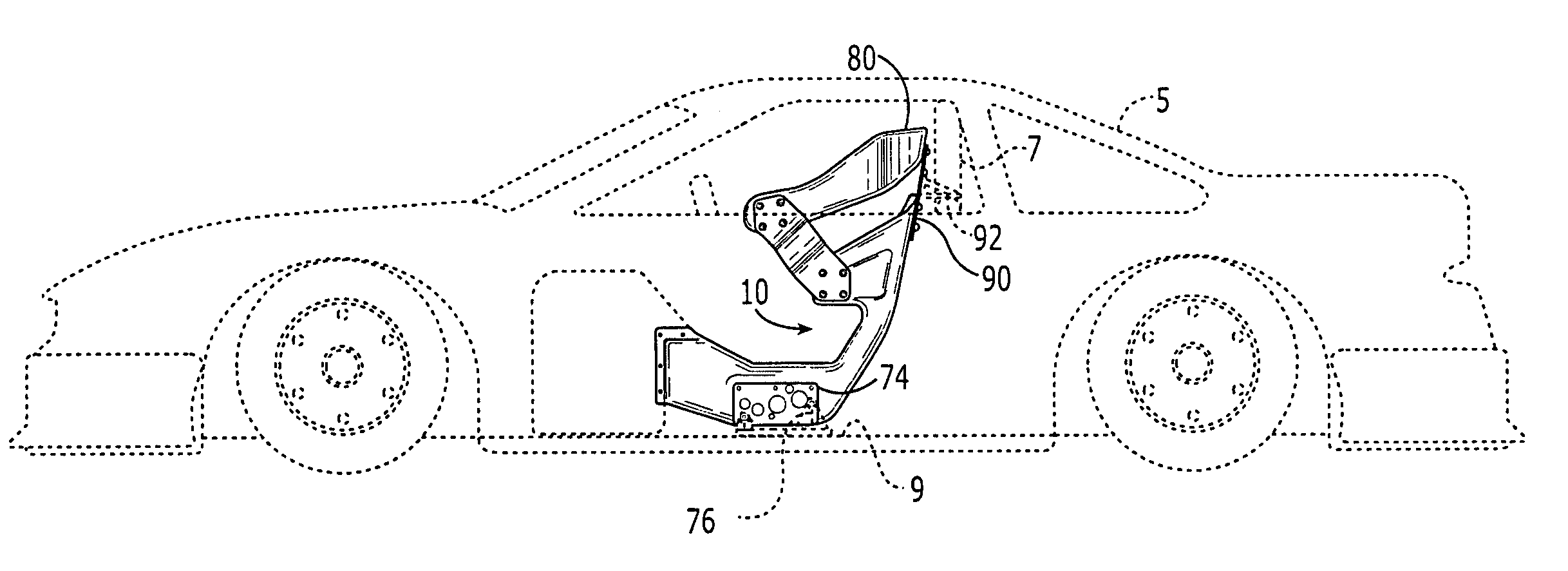
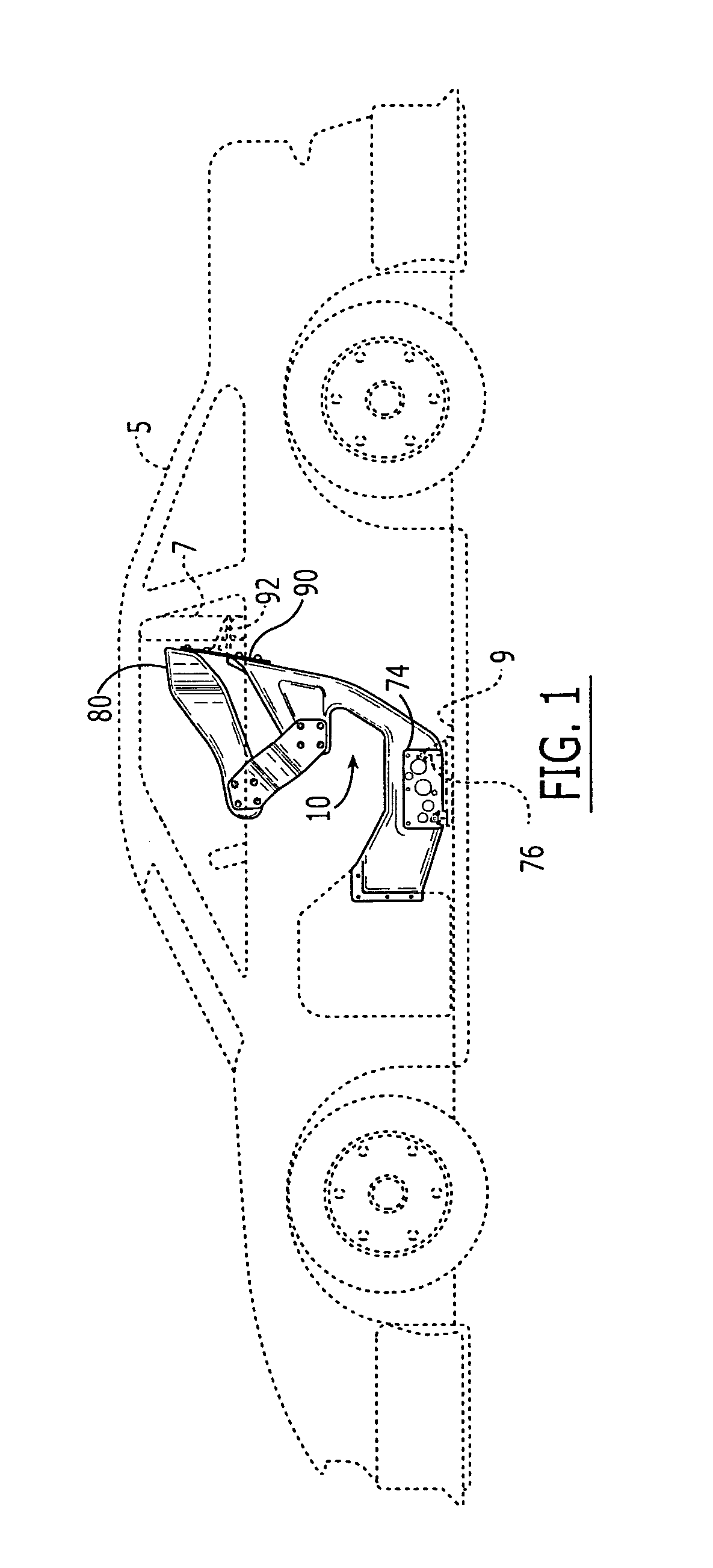
[0023]Referring to FIG. 1, a safety seat 10 is positioned within a vehicle 5 and attached to certain structural members of the vehicle 5, e.g., a roll cage 7 and floor frame 9, by mounting brackets 76, 92 fastened to support plates 74, 90 that are attached to the safety seat 10. In a preferred embodiment, headrest 80 is attached to the safety seat 10.

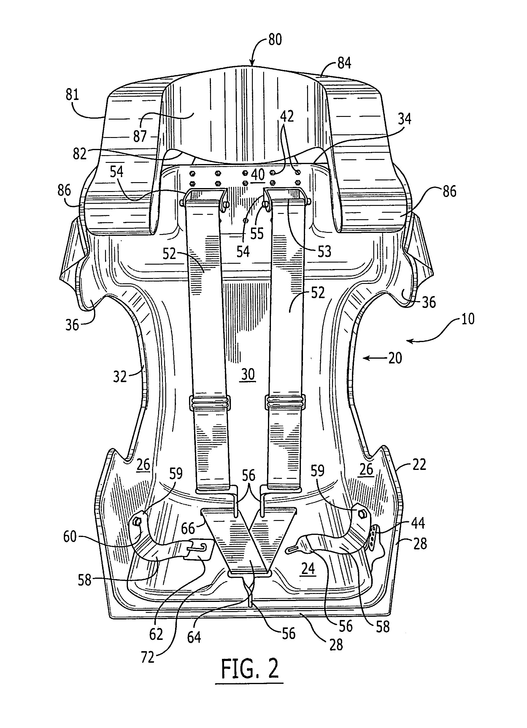
[0024]As shown in FIG. 2, the safety seat 10 includes a unitary molded shell 20, a safety restraint system integral to the shell 20 and padding 70 disposed on a seating surface 110 of the shell 20 (as illustrated in FIG. 5). The shell 20 has a bottom portion 22 that seamlessly merges into a back portion 30 such that the shell 20 has a “bucket-seat” type shape. The bottom portion 22 is U-shaped with a base 24 and opposing sides 26 extending generally perpendicularly from the base 24, the base being generally horizontal. The base 24 and sides 26 have a front edge 28 opposite the back portion 30 of the shell 20. The back portion 30 extends...


PUM

PropertyMeasurementUnit
thickaaaaaaaaaa
pressureaaaaaaaaaa
forcesaaaaaaaaaa

Abstract

A safety seat comprising a unitary molded shell having a “bucket-seat” shape and a safety restraint system integral to the shell. The molded unitary shell has a bottom portion and a back portion. The shell comprises an inner layer and an outer layer made of a carbon fiber laminate with a core situated between the inner and outer layers. The core comprises aluminum sheeting having a honeycomb-like cross-section. A plurality of attachment plates are selectively located within the shell and disposed between the inner and outer layers. The safety restraint system is fastened to corresponding attachment plates. Support plates located on a non-seating surface of the shell are mated with selected attachment plates. A headrest is selectively attached to the safety seat. The safety seat is secured to structural members within a vehicle by mounting brackets. A method for making the shell and assembling the safety seat are disclosed.

Description

[0001]This application is a divisional of U.S. patent application Ser. No. 10 / 657,970, filed Sep. 9, 2003, for MOLDED SAFETY SEAT co-pending herewith.BACKGROUND OF INVENTION[0002]The present invention relates to occupant safety devices within vehicles, and more particularly molded safety seats used in race cars, and methods of making and using said safety seats.[0003]Vehicles provide convenient and usually safe transportation. Since almost the introduction of the automobile, people have been racing them, the goal being faster than one's competitors. The automobiles used for racing range from specially built futuristic designs to cars and trucks that have at least a passing resemblance to those driven on ordinary streets.[0004]One concept that is similar in both racing and ordinary automobiles is the safety of occupants during collisions. Although the types of collisions experienced on ordinary streets and race tracks are similar, i.e., car-to-car collisions, car-to-barrier collision...

Claims


Application Information

Patent Timeline
Patent Type & Authority Patents(United States)
IPC IPC(8): B60N2/005B60N2/015B60N2/70B60N2/48B60N2/44B60N2/90
CPCB60N2/015B60N2/449B60N2/4802B60N2/4882B60N2/7011Y10T428/24149Y10T156/1028Y10T29/49826Y10T29/4998Y10T29/49838B60N2/803B60N2/885B60N2/986
Inventor DEHART, GARY GENE
Owner HMS HLDG LLC
Learn More