Bi-aspherical type progressive-power lens

a technology of progressive power and lens, applied in the field of biaspherical type progressive power lens, can solve the problems of insufficient prior art from a viewpoint, inability to accurately calculate the “magnification, and wearer to feel distortion or sway of an image, so as to achieve excellent visual field, improve labor efficiency, and improve the effect of visual field

Inactive Publication Date: 2005-08-30
HOYA CORP
View PDF21 Cites 24 Cited by
  • Summary
  • Abstract
  • Description
  • Claims
  • Application Information

AI Technical Summary

Benefits of technology

[0061]It is generally known that an excellent visual field in the horizontal direction has its limits since there is astigmatism in the peripheral portion of the “progressive surface,” but if the “progressive surface” is placed on the eyeball side surface, the “progressive surface” itself approaches the eye to present an advantage that the excellent visual filed is widened in the horizontal direction. On the other hand, this results in a further distance between the distance and near visual regions in the vertical direction to present a disadvantage that a labor increases in rotating the eye from the far vision to the near vision. In other words, the rear surface progression (or concave surface progression), as compared to the conventional front surface progression (or convex surface progression), presents an advantage of widening the visual field in the horizontal direction but a disadvantage of increasing the rotating angle of the eye from the far vision to the near vision in the vertical direction.
[0062]The present invention, however, includes the progressive refracting surface which satisfies the relational equations DHf+DHn<DVf+DVn and DHn<DVn, or DVn−DVf>ADD / 2 and DHn−DHf<ADD / 2 as described above, and thus the present invention has characteristics created by the rear surface progression (or concave surface progression) greater than those by the conventional front surface progression (or convex surface progression) in the horizontal direction, and characteristics created by the conventional front surface progression (or convex surface progression) greater than those by the rear surface progression (or concave surface progression) in the vertical direction. Therefore, according to the present invention, it is possible to restrain the disadvantage of increasing the eyeball rotating angle between the distance and near portions in the vertical direction while receiving the advantage of increasing the visual field in the horizontal direction.
[0063]Further, in an extreme example within the scope of the present invention, when DVn−DVf=ADD and DHn−DHf=0, a lens has progressions identical to the conventional front surface progression (or convex surface progression) in the vertical direction and to the rear surface progression (or concave surface progression) in the horizontal direction. Therefore, this case presents an extremely excellent result that the advantage in the horizontal direction can be obtained without the disadvantage in the vertical direction.
[0064]Further, these things also apply to decreasing the magnification difference of an image between the distance portion and the near portion and improving the distortion and sway of the image as described above, and thus they can be advantages of the present invention.

Problems solved by technology

However, it is also widely known that the necessity of arrangement of a plurality of visual fields such as a field for looking far and a field for looking near, and further a field for looking at a distance intermediate therebetween, without a boundary line existing within a limited lens area, presents disadvantages specific to the progressive-power lens such that each visual field is not always sufficiently wide, and that there is a region mainly in a side visual field which causes the wearer to feel distortion or sway of an image.
Accordingly, the lens design of Prior art 1 has a possibility of error caused by the “calculation of the lens magnification without consideration of the angle between a sight line and a lens surface.”c. Prior art 1 only describes the “magnification” for an application example to a cylindrical lens but lacks idea on direction thereof, which causes a possibility of error when “magnifications in the vertical direction and the horizontal direction are different” which occurs, for example, in the near portion positioned at a great distance below the lens center.d.
In Prior art 1, the “object distance” is not taken into consideration, which presents an undeniable possibility of error.e.
In the magnification calculations, the influence by a prism action is not taken into consideration, which may cause an error.
As described above, the prior art may not be always sufficient from a viewpoint, in particular, of more accurately calculating the “magnification.”

Method used


Image

  • Bi-aspherical type progressive-power lens
  • Bi-aspherical type progressive-power lens
  • Bi-aspherical type progressive-power lens

Examples


example 1

[0141]Table 1-1 in FIG. 7 is a list regarding the surface refractive powers of Example 1 according to the present invention. The diopters of Example 1 correspond to S being 0.00 and ADD being 3.00, with three kinds of prior art examples having the same diopters being listed together for comparison. It should be noted that Prior art example A, Prior art example B, and Prior art example C correspond to a “convex surface progressive-power lens” in which the object side surface is a progressive surface, a “bi-surface progressive-power lens” in which both the object side surface and eyeball side surface are progressive surfaces, and a “concave surface progressive-power lens” in which the eyeball side surface is a progressive surface, respectively. Meanings of items used in Table 1-1 are as follows:

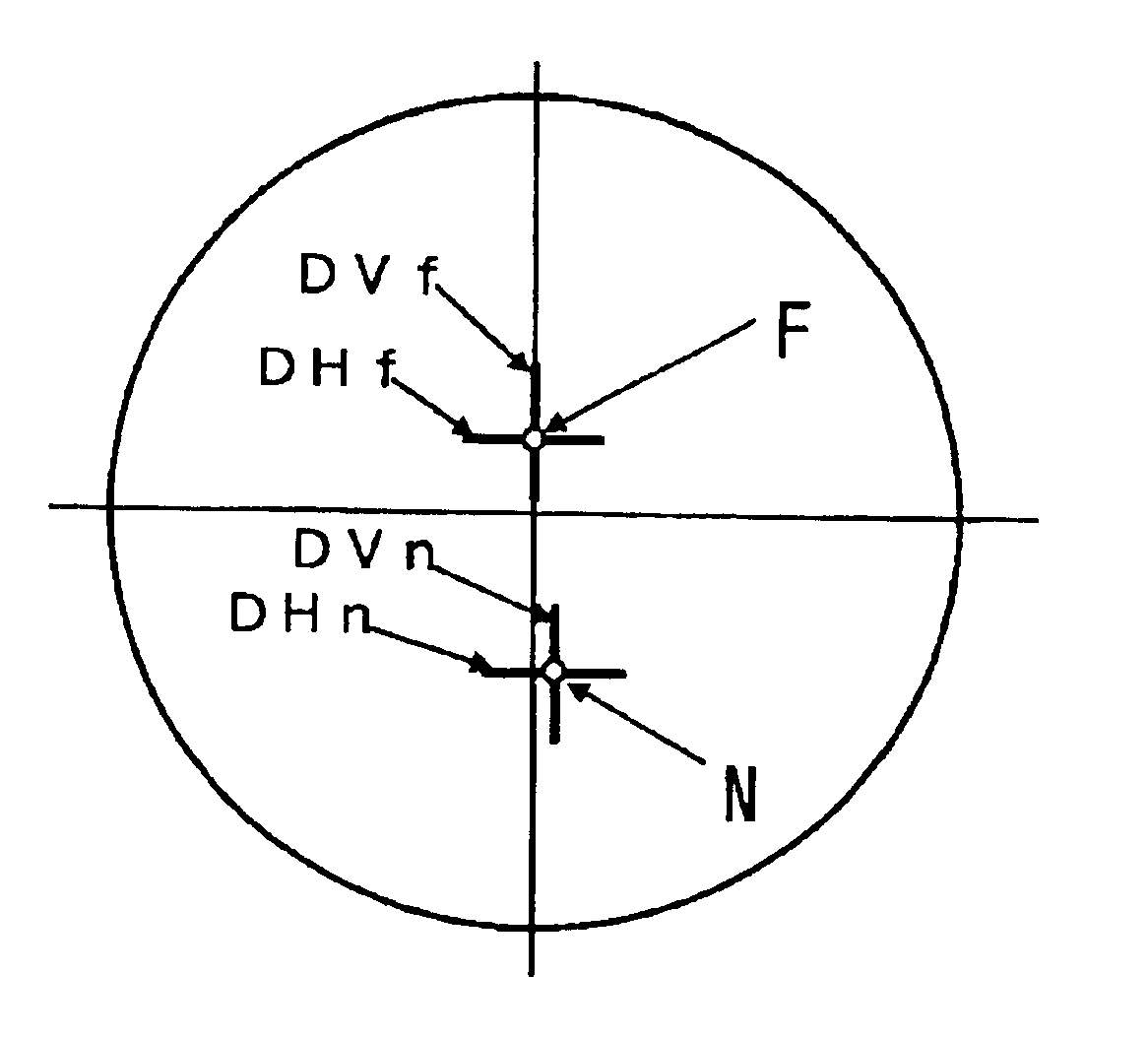
[0142]DVf1: surface refractive power in the vertical direction at a far vision diopter measurement position F1 on the object side surface,

[0143]DHf1: surface refractive power in the horizontal ...

example 2

[0181]Table 2-1 in FIG. 8 is a list regarding the surface refractive powers of Example 2 according to the present invention. The diopters of Example 2 correspond to S being +6.00 and ADD being 3.00, with three kinds of prior art examples having the same diopters being listed together for comparison. It should be noted that Prior art example A, Prior art example B, and Prior art example C correspond to a “convex surface progressive-power lens” in which the object side surface is a progressive surface, a “bi-surface progressive-power lens” in which both the object side surface and eyeball side surface are progressive surfaces, and a “concave surface progressive-power lens in which the eyeball side surface is a progressive surface, respectively. Meanings of terms such as DVf1 to DHn2 used in Table 2-1 are the same as those in the above-described Table 1-1. Graphs 2-1 and 2-2 are graphs showing the surface refractive power distributions along the main gazing lines of Example 2 according...

example 3

[0188]Table 3-1 in FIG. 9 is a list regarding the surface refractive powers of Example 3 according to the present invention. The diopters of Example 3 correspond to S being −6.00 and ADD being 3.00, with three kinds of prior art examples having the same diopters being listed together for comparison. It should be noted that Prior art example A, Prior art example B, and Prior art example C correspond to a “convex surface progressive-power lens” in which the object side surface is a progressive surface, a “bi-surface progressive power lens” in which both the object side surface and eyeball side surface are progressive surfaces, and a “concave surface progressive-power lens in which the eyeball side surface is a progressive surface, respectively. Meanings of terms such as DVf1 to DHn2 used in Table 3-1 are the same as those in the above-described Table 1-1 and Table 2-1.

[0189]Graphs 3-1 and 3-2 in FIG. 11 are graphs showing the surface refractive power distributions along the main gazin...


PUM


Abstract

To provide a bi-aspherical type progressive-power lens which provides an excellent visual acuity correction for prescription values and a wide effective visual field with less distortion in wearing, by reducing a magnification difference of an image between a distance portion and a near portion. The lens is characterized in that when on a first refractive surface being an object side surface, a surface refractive power in a horizontal direction and a surface refractive power in a vertical direction, at a far vision diopter measurement position F1, are DHf and DVf respectively, and on the first refractive surface, a surface refractive power in a horizontal direction and a surface refractive power in a vertical direction, at a near vision diopter measurement position N1, are DHn and DVn respectively, relational equations,
DHf+DHn<Dvf+DVn, and DHn<DVn
are satisfied, and surface astigmatism components at F1 and N1 of the first refractive surface are cancelled by the second refractive surface being an eyeball side surface so that the first and second refractive surfaces together provide a far vision diopter (Df) and an addition diopter (ADD) based on prescription values.

Description

TECHNICAL FIELD[0001]The present invention relates to a bi-aspherical type progressive-power lens, which is a lens used as, for example, a progressive-power lens for a spectacle for presbyopia that is configured to have a progressive refractive power action dividedly allotted to a first refractive surface being an object side surface and a second refractive surface being an eyeball side surface, so that the first surface and the second surface together provide a far vision diopter (Df) and an addition diopter (ADD) based on prescription values.BACKGROUND ART[0002]A progressive-power lens is widely used in general because of an advantage that it is hardly detected from others as a spectacle for the aged in spite of a spectacle lens for presbyopia, an advantage that it allows a wearer to clearly look continuously from a far distance to a near distance without discontinuity, and so on. However, it is also widely known that the necessity of arrangement of a plurality of visual fields su...

Claims


Application Information

Patent Timeline
Patent Type & Authority Patents(United States)
IPC IPC(8): G02C7/02
CPCG02C7/021G02C7/061G02C7/063G02C7/068G02C7/06
Inventor KITANI, AKIRAKIKUCHI, YOSHIHIRO
Owner HOYA CORP
Why Eureka
Try Eureka