
Pluggable optical transceiver latch

a technology of optical transceivers and latches, which is applied in the direction of optical elements, coupling device connections, instruments, etc., can solve the problems of electro-magnetic interference (emi) leakage, and the weight of the module is not sufficiently robus

Inactive Publication Date: 2005-08-30
LUMENTUM OPERATIONS LLC
View PDF6 Cites 74 Cited by
  • Summary
  • Abstract
  • Description
  • Claims
  • Application Information

AI Technical Summary

Benefits of technology

[0017]a first camming surface on the first lever for engaging the first arm when the slide is in the unlatch position, thereby pivoting the first latch hook out of engagement with the first latching surface enabling removal of the module from the host device.

Problems solved by technology

Unfortunately, all of the conventional latch devices were developed for relatively small, lightweight modules, and therefore not sufficiently robust for heavier modules.
Moreover, conventional transceivers are mounted almost flush with a front face of the host device leaving very little of the module to grasp, while leaving gaps resulting in electro-magnetic interference (EMI) leakage.

Method used


Image

  • Pluggable optical transceiver latch
  • Pluggable optical transceiver latch
  • Pluggable optical transceiver latch

Examples


Embodiment Construction

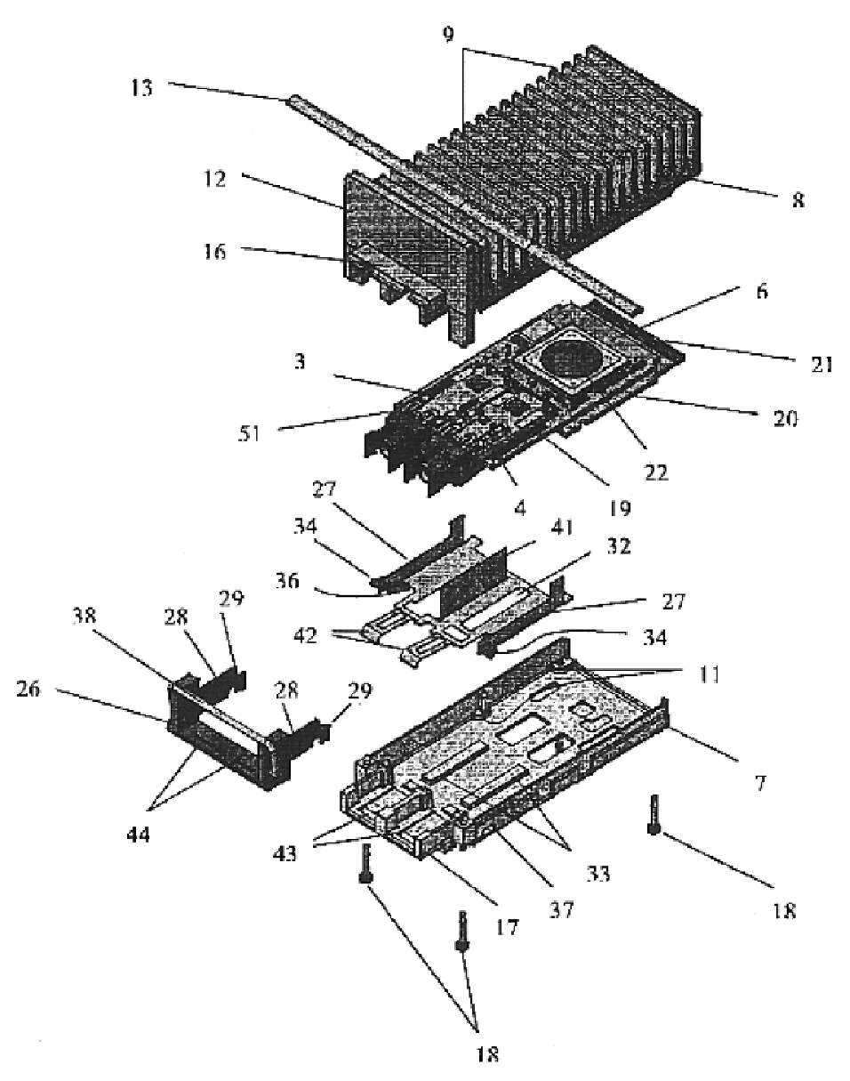
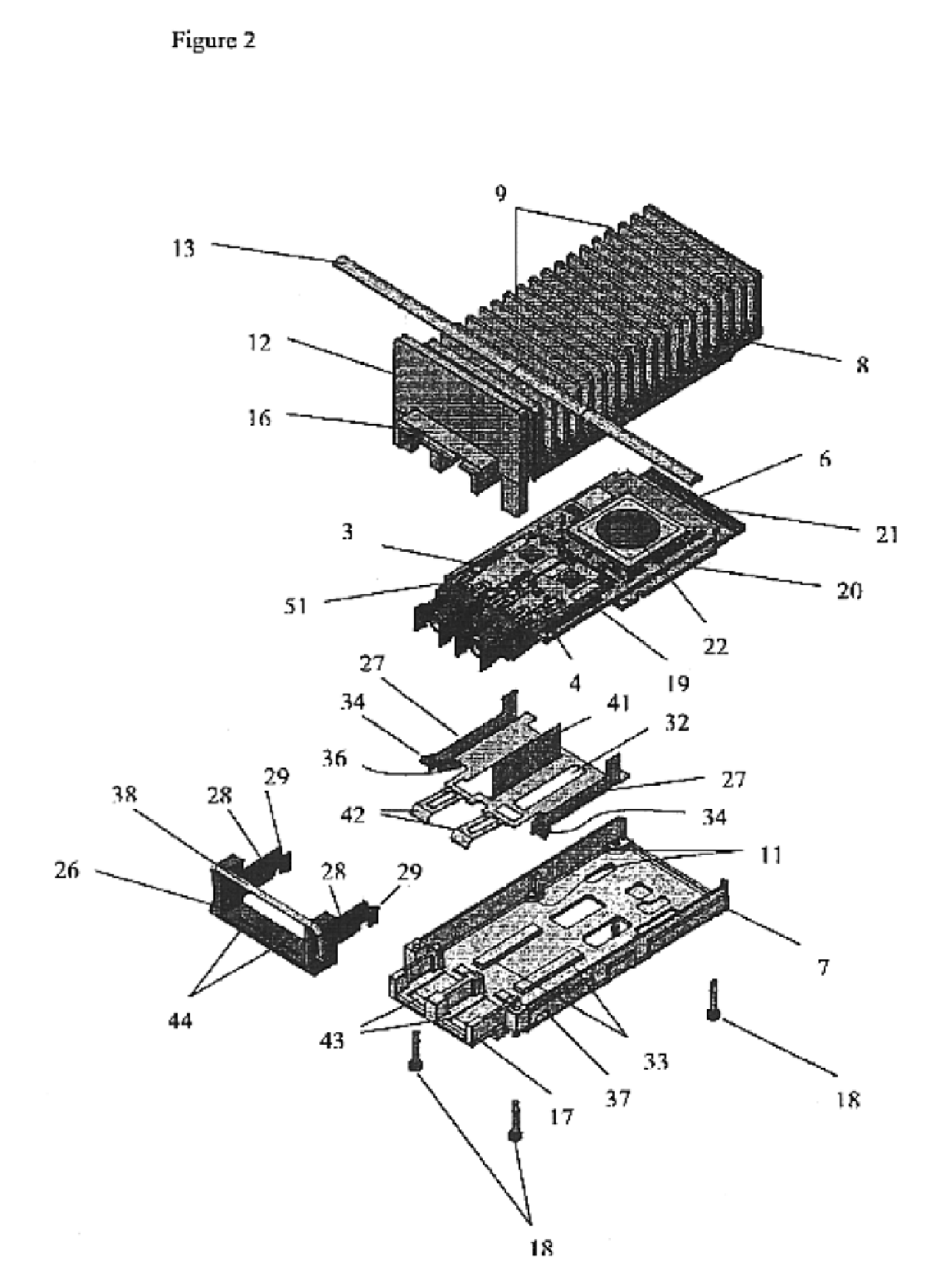
[0040]With reference to FIGS. 1, 2, 3 and 4, the pluggable optical transceiver 1 according to the present invention includes a module housing 2, which supports a ROSA 3, a TOSA 4, and a printed circuit board 6. The housing 2 is comprised of a base 7 and a heat-dissipating cover 8, which includes a plurality of heat sink fins 9. A plurality of lands 11 extend from the base 7 for supporting the printed circuit board 6. A flange 12 is provided on the cover 8 for abutting a front face plate disposed on the host device, when the module is inserted therein. The flange 12 has dimensions that are taller and wider than those of the remainder of the housing 2 to provide a shield against electro-magnetic interference (EMI). A gasket 13 is wrapped around the housing 2 between the flange 12 and the host device face plate to further limit the passage of EMI. The gasket 13 can be either a foam conductive strip or a plurality of spring fingers. A snout 14, extending from the flange 12, is formed by...


PUM


Abstract

The invention relates to a latch device for a pluggable opto-electronic module, such as an optical transceiver, for locking the module in a rail or cage system of a host machine. The latest generation of optical transceivers include all metal housings, instead of all plastic or partial plastic, to ensure adequate heat dissipation. The relatively heavier housings necessitate the use of more robust latch devices. The latch device according to the present invention includes a sliding element with arms extending therefrom for pivoting a latching hook out of engagement with the rail or cage system. In a preferred embodiment, a pair of latching hooks are provided, one on each side of the module. The latching hooks are mounted on the ends of spring arms, which extend from the same sheet of spring metal positioned across the bottom of the housing.

Description

CROSS-REFERENCE TO RELATED APPLICATIONS[0001]The present invention claims priority from U.S. patent applications Ser. Nos. 60 / 390,147 filed Jun. 21, 2002; 60 / 392,353 filed Jul. 1, 2002; 60 / 405,718 filed Aug. 26, 2002; and 60 / 453,654 filed Mar. 11, 2003.TECHNICAL FIELD[0002]The present invention relates to a latch for a pluggable optical transceiver, and in particular to a latch for facilitating removal of the transceiver from a guide rail or cage of a host device.BACKGROUND OF THE INVENTION[0003]Conventional optical transceivers include a transmitter optical subassembly (TOSA) and a receiver optical subassembly (ROSA) connected to a printed circuit board for transmitting and receiving optical signals, respectively, between an optical network and a host device. A “hot pluggable” optical transceiver includes an electronic connector electrically connected to the printed circuit board for mating with a corresponding optical coupler mounted on a printed circuit board in the host device. ...

Claims


Application Information

Patent Timeline
IPC IPC(8): G02B6/42
CPCG02B6/4292
Inventor HANLEY, MICHAEL FRANCISMALAGRINO JR., GERALD DANIEL
Owner LUMENTUM OPERATIONS LLC
Features
  • Generate Ideas
  • Intellectual Property
  • Life Sciences
  • Materials
  • Tech Scout
  • Unparalleled Data Quality
  • Higher Quality Content
  • 60% Fewer Hallucinations
Learn More