Electric connector

a technology of electrical connectors and connectors, applied in the direction of coupling contact members, coupling device connections, incorrect coupling prevention, etc., can solve problems such as preventing good electrical connections, and achieve the effects of facilitating the design and manufacture of both components, good wiping action, and increasing flexibility in creating

Inactive Publication Date: 2005-08-30
JST MFG CO LTD
View PDF27 Cites 25 Cited by
  • Summary
  • Abstract
  • Description
  • Claims
  • Application Information

AI Technical Summary

Benefits of technology

[0010]Further, the second object of the present invention is to provide an electric connector that can be firmly affixed onto a circuit board.
[0027]Further, according to the electric connector of another mode of the present invention, good wiping action can be achieved by selecting the predetermined angle from within the range of 6° to 15°. In addition, since a plurality of supporting protrusions are provided on the lower wall portion on the rear side of the housing, the supporting protrusions abut on the circuit board surface even when the terminal of the battery and the like pushes the pin-shaped contact when force is applied, making the housing draw away from the circuit board, thereby preventing the housing from being peeled off from the circuit board.
[0028]Furthermore, according to the electric connector of another mode of the present invention, the terminal portion is separated from the probe-type contact, which facilitates the design and manufacturing of both components. Additionally, since various types of separate connecting portions can be formed, it is possible to draw out the terminal from the housing in any direction (whether upward, downward, rightward, leftward or rearward), thereby increasing flexibility in creating the layout design of equipment for mounting the electric connector.
[0029]Further still, according to the electric connector of another mode of the present invention, the contact is connected to the tubular body of the probe-type contact in such manner as to be freely detachable, making for easier assembly and allowing replacement of components as well as facilitating repair. Moreover, since the contact is made of a circular ring, attachment or detachment thereof from the probe-type contact becomes effortless.
[0030]Further, according to the electric connector of another mode of the present invention, connection with the circuit board can be achieved by a plurality of the connecting pieces provided at the L-shaped base in a staggered state. Therefore, the number of connecting points is increased, and even if connection failure occurs on one connecting piece, the existence of other connecting pieces practically eliminates the occurrence of almost all connection failures. In addition, the connection made by the connecting pieces serves as the mode of attaching of the connector housing to the circuit board, and therefore providing means for affixing the housing is not necessary.

Problems solved by technology

However, there are cases where dust and the like adheres to or an oxide film is formed on the terminal surface of the battery, causing contact failure, thereby preventing good electrical connection.

Method used


Image

  • Electric connector
  • Electric connector
  • Electric connector

Examples


example 1

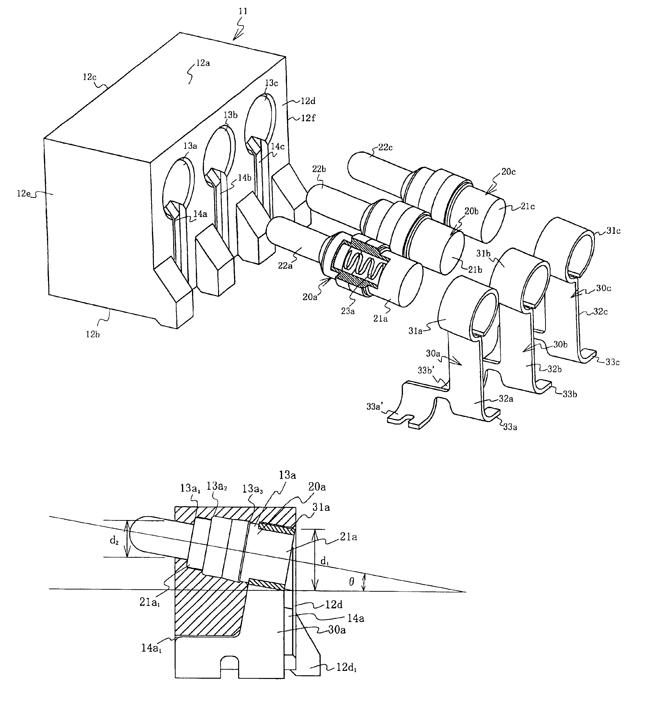
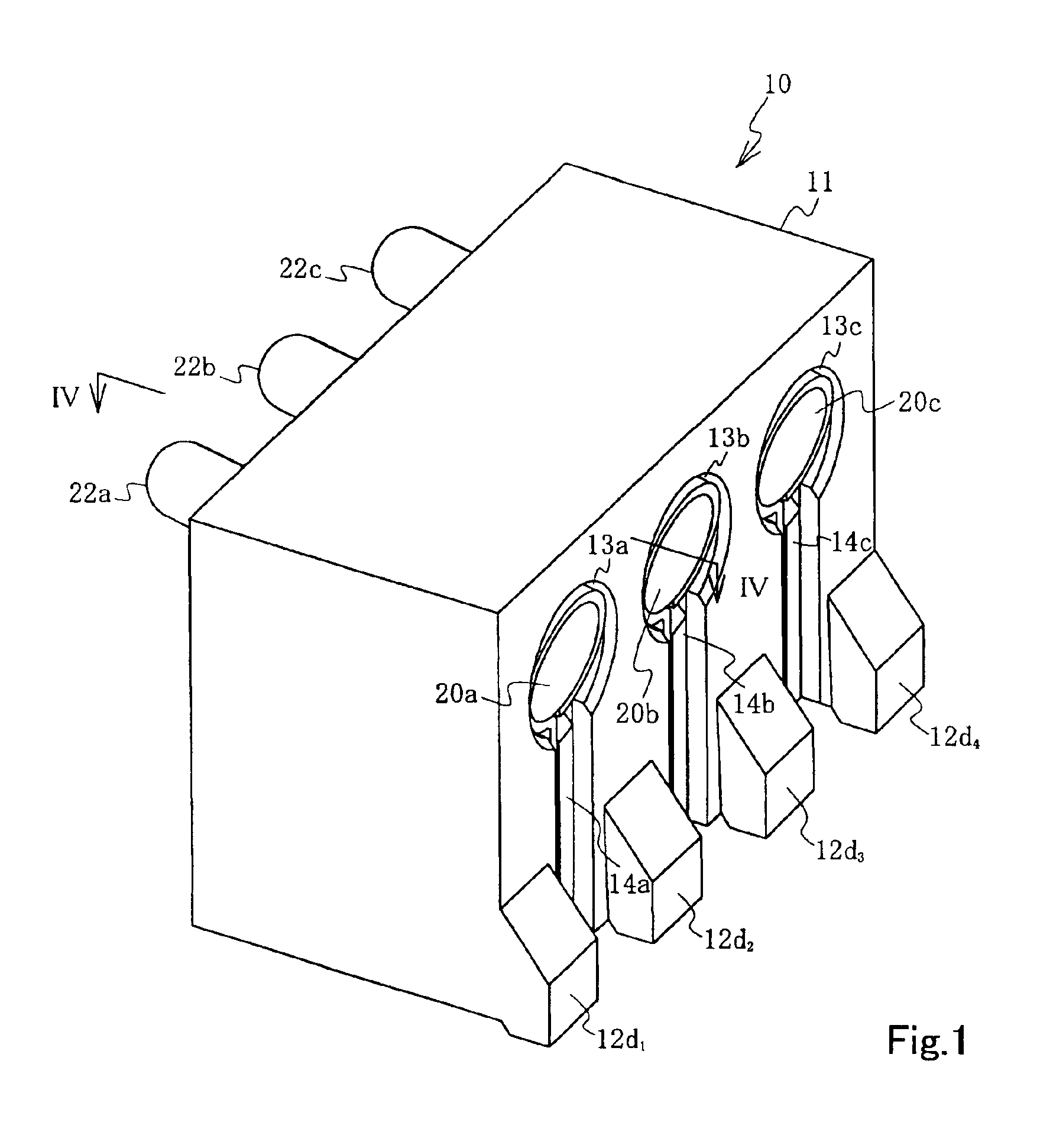
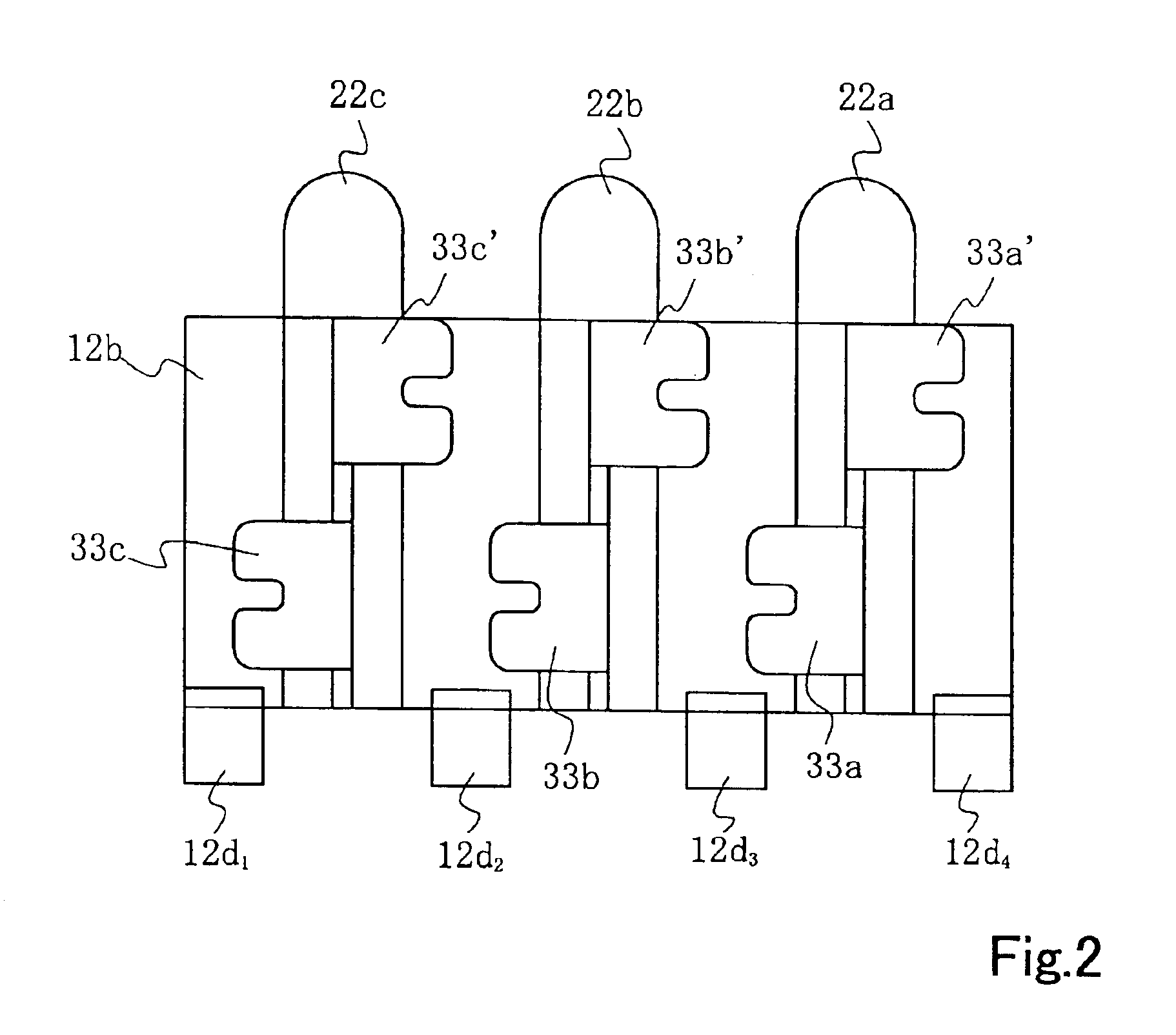
[0041]FIG. 1 is a perspective of the external view of the electric connector of the present invention, while FIG. 2 is the bottom surface view of the electric connector and FIG. 3 is an exploded view of the electric connector shown in FIG. 1. FIG. 4 is the sectional view at IV—IV of FIG. 1, while FIG. 5A, FIG. 5B and FIG. 5C respectively show the front, right side and bottom surface views of the terminal portion of FIG. 3. FIG. 6 is a side view of the probe-type contact, and FIG. 7 is a side view showing the state of connection between the electric connector and equipment.

[0042]An electric connector 10 is provided with a housing 11 having three through holes 13a to 13c, probe-type contacts 20a to 20c inserted into each through hole, and terminal portions 30a to 30c connected to each probe-type contact. The probe-type contacts 20a to 20c are constituted as follows. Pin-shaped contacts 22a to 22c are housed in conductive tubular bodies 21a to 21c in such manner as to move freely back ...


PUM


Abstract

An electric connector using a probe-type contact(s) is provided to prevent it from having contact failure and is characterized in that it comprises a housing having at least one through hole, a probe-type contact(s) inserted into the through hole(s), and a terminal portion(s) connected to the probe-type contact(s). In the probe-type contact, a pin-shaped contact(s) is housed in a conductive tubular body in such manner that the contact is energized to move freely by a spring. The tip of the pin-shaped contact is tilted upward at a predetermined angle in a horizontal direction, and is installed into the through hole so as to protrude from the front wall surface of the housing.

Description

BACKGROUND OF THE INVENTION[0001]1. Field of the Invention[0002]The present invention relates to an electric connector, more particularly to the modification of an electric connector using a contact(s) where a pin-shaped contact(s) is housed in a conductive tubular body (bodies) in such manner that the contact(s) is energized to move freely back and forth by a spring(s), which is a so-called probe-type contact.[0003]2. Prior Art[0004]First, an electric connector using a conventional probe-type joint will be described using a drawing. FIG. 8A and FIG. 8B shows the electric connector using the probe-type contact described in Japanese Patent Laid-Open Publication No. 11-149954 publication (Refer to FIG. 6, right column on page 3.), in which FIG. 8A and FIG. 8B respectively show the sectional view of the contact and the side view showing the state of connection of the electric connector with particular equipment.[0005]In the probe-type contact 2, as shown in FIG. 8A and FIG. 8B, a condu...

Claims


Application Information

Patent Timeline
Patent Type & Authority Patents(United States)
IPC IPC(8): H01R13/24H01R13/22H01R12/71H01R13/64H01R13/187
CPCH01R13/2421H01R12/57H01R13/64H01R13/187
Inventor ORIHARA, MASAYUKI
Owner JST MFG CO LTD
Why Eureka
Try Eureka