Endovascular guidewire filter and methods of use

a technology of endovascular guidewire and filter, which is applied in the field of endovascular guidewire filter and method of use, can solve the problems of occlusion of narrower vessels downstream, ischemia or infarct of the organ which the vessel supplies, and difficulty in insertion of the filter through a complex vascular lesion, so as to prevent accidental release of emboli, minimize neurologic, cognitive and cardiac complications, and tight stowage of the filter

Inactive Publication Date: 2005-08-30
BOSTON SCI SCIMED INC
View PDF238 Cites 135 Cited by
  • Summary
  • Abstract
  • Description
  • Claims
  • Application Information

AI Technical Summary

Benefits of technology

[0012]In another embodiment, the device comprises first and second elongate members. The second elongate member is slideably disposed within a lumen of the first elongate member. The proximal ends of the first and second flexible members are fixed to the second elongate member, and the distal ends of the flexible members are fixed to the first elongate member. The flexible members are operated by sliding the second elongate member distally within the first elongate member, thereby advancing the flexible members through the proximal ports and placing the filter in an expanded state.
[0014]In another embodiment, a plurality of tethers are coupled at a first end to the distal end of the elongate member, and the second end of each of the tethers is coupled to the edge of a parachute filter. In certain embodiments the edge of the filter is mounted about a circular rim. An independently moveable tether is also coupled to the filter edge or the circular rim and is operable at a proximal end. A capture sheath, slideably disposed over the filter and the circular rim, assists in stowing the filter and prevents accidental dislodgment of embolic material during filter closure. The circular rim or filter edge can be rotated into alignment substantially parallel with the elongate member and capture sheath by withdrawing proximally the independently moveable tether. In some embodiments, the circular rim is constructed of a superelastic material, e.g., nitinol. This alignment enables the capture sheath to cover the filter and circular rim to assist with removal of the filter from the vessel.
[0015]In another embodiment, the filter is attached to the elongate member by a plurality of flexible struts. Each of the flexible struts is coupled at a first end to the distal end of the elongate member and coupled at a second end to the filter. The filter is contracted by rotating the elongate member, which in turn winds the flexible struts. A capture sheath is disposed about the elongate member and the filter for stowage of the filter. As the flexible struts wind, the filter is closed, and the capture sheath is able to cover the flexible struts and filter to assist in removal from the vessel.
[0017]In a first method of using the filter device having first and second flexible members, the filter is placed in a contracted state. The distal end of the tubular member is inserted percutaneously through an artery or vein and advanced into or beyond a region of interest, typically a stenotic lesion caused by buildup of atherosclerotic plaque and / or thrombi. The filter is then expanded downstream of the vascular occlusion by operating the first and second flexible members. In this way, the filter structure conforms to the interior vessel wall with minimum gap, as the elongate tubular member lies against the luminal wall of the vessel. The elongate tubular member then acts as a platform, or guidewire, to guide therapeutic instruments to operate on the stenosis within the region of interest. After the stenotic lesion is removed by endovascular procedure(s), e.g., angioplasty, atherectomy, or stent deployment, the filter is collapsed and removed from the vessel, together with the captured embolic debris. When the filter is stowed, the flexible members are tightened against the tubular member and constricted by a capture sheath advanced distally over the filter during closure, creating a controlled closure of the filter. In this way, bunching of the filter and undesired release of the captured embolic debris are avoided.
[0020]In another method, using the filter device having a filter coupled to the elongate member by a plurality of flexible struts, the distal end of the elongate member is advanced to a region of interest within a patient's vessel. The capture sheath is withdrawn to release the filter, thereby expanding the filter within the region of interest. After completion of endovascular procedures, the elongate member is rotated, thereby winding the plurality of flexible struts to contract the filter. The capture sheath is advanced distally to cover the wound flexible struts and the filter, thereby providing tight stowage of the filter and preventing accidental release of captured emboli.
[0021]It will be understood that there are several advantages to using the filter devices and methods disclosed herein for capturing and removing embolic debris during endovascular procedures. For example, the filter devices (1) are particularly well suited for temporary filtration of blood in any vessel to entrap embolic debris, thereby minimizing neurologic, cognitive, and cardiac complications associated with distal embolization, (2) conform to the interior vessel wall with minimum gap, (3) can be collapsed to a uniform and predictable size, (4) can be delivered over a guidewire as a rapid exchange device, (5) can be delivered through a lumen of an angioplasty or stent deployment device, (6) may include an atraumatic distal tip to minimize vessel wall injury, (7) enable an operator to steer and deploy the filter without kinking, bending, and / or looping of the catheter because of the small size ratio of filter to catheter, (8) can pass a large occluding lesion due to their small diameter when collapsed, (9) can be used as a guidewire over which a therapeutic catheter may be advanced, and (10) can be used in adult and pediatric patients.

Problems solved by technology

It is well recognized that one of the complications associated with endovascular techniques is the dislodgment of embolic materials generated during manipulation of the vessel, thereby causing occlusion of the narrower vessels downstream and ischemia or infarct of the organ which the vessel supplies.
Microemboli, as detected by transcranial Doppler monitoring in this study, have been shown to be a potential cause of stroke.
However, there are several disadvantages associated with guidewire-filtration.
First, the steerability of the guidewire may be altered as compared to conventional guidewires due to the size of the filter, and the guidewire may bend, kink, and / or loop around in the vessel, making insertion of the filter through a complex vascular lesion difficult.
Secondly, the current filter designs, e.g., a basket or net, often fail to conform to the internal perimeter of the vessel, and distal embolization can still occur despite the filter placement.
Thirdly, as the filter is stowed, the filter material is gathered together with “bunching” of the material at the perimeter, causing uncontrolled gathering and creating relatively large and poorly defined crossing profiles.
As a result, the current filter designs require large capture sheaths to deploy and stow the filter.
Existing devices are inadequate for this purpose.

Method used


Image

  • Endovascular guidewire filter and methods of use
  • Endovascular guidewire filter and methods of use
  • Endovascular guidewire filter and methods of use

Examples


Embodiment Construction

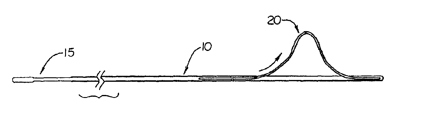
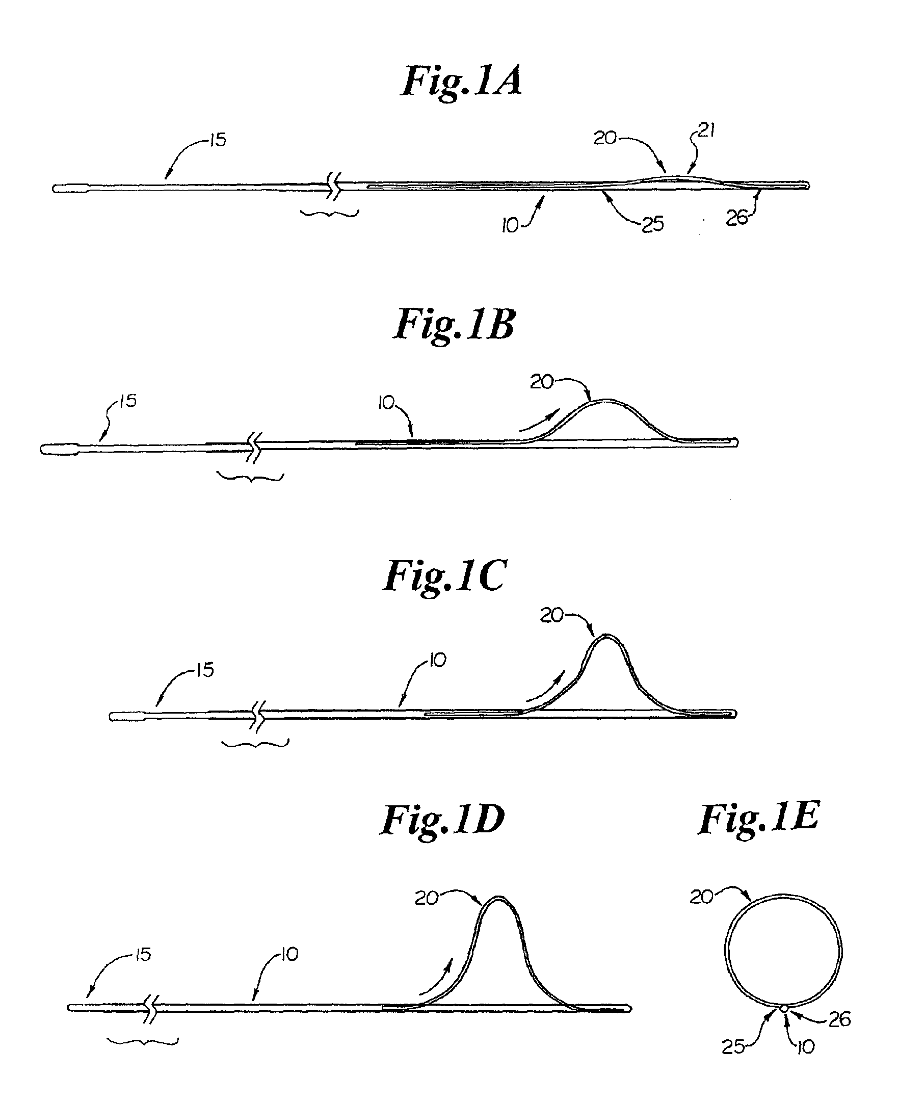
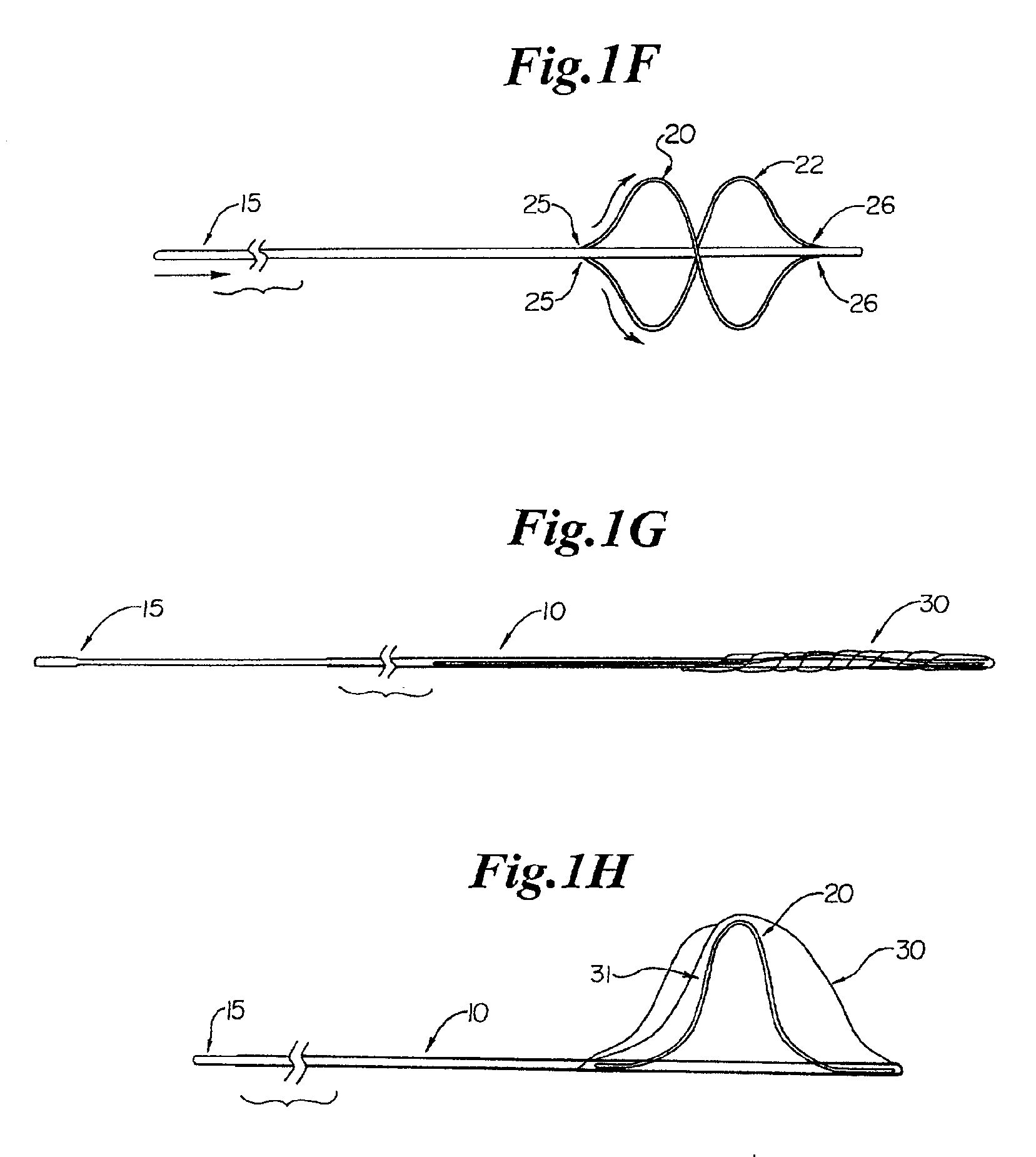
[0064]A filter device for temporary placement in a vessel, either an artery or vein, is provided as depicted in FIGS. 1A through 1H. FIG. 1A shows elongate tubular member 10 having proximal ports 25 and distal ports 26 located at a distal region. Proximal ports 25 are located circumferentially approximately 180° from each other. Distal ports 25 are also located circumferentially approximately 180° from each other. The circumferential positioning, however, may vary between 90° and 270°, more preferably 100° to 260°, more preferably 110° to 250°, more preferably 120° to 240°, more preferably 130° to 230°, more preferably 140° to 220°, more preferably 150° to 210°, more preferably 160° to 200°, more preferably 170° to 190°, most preferably approximately 180°.

[0065]A first flexible member 20 passes through port 25 at a proximal end, crosses 180° over elongate member 10 at point 21, and either is coupled externally at the distal end of elongate member 10 (not shown), or passes through di...


PUM


Abstract

A filter device for temporary placement of a filter in an artery or vein is disclosed. The devices include (1) an elongate tubular member having a single or double side-wire loop, (2) an elongate member having a filter bonded to a circular rim joined by a plurality of tethers and an independently moveable tether, and (3) an elongate member having a parachute filter joined by a plurality of flexible struts. The filter conforms to the interior of a vessel wall when expanded and contracts to a consistent diameter without bunching when stowed. The filter devices may act as guidewires for guiding a therapeutic catheter to a region of interest within a vessel. Methods of using the filter device to entrap and remove embolic material from a vessel during endovascular procedures are also disclosed.

Description

[0001]This application hereby claims the benefit under Title 35, United States Code, §119(e) of U.S. Provisional Application Ser. No. 60 / 262,135 filed on Jan. 16, 2001.FIELD OF THE INVENTION[0002]The present invention relates generally to devices and methods for providing temporary placement of a filter in a blood vessel. More particularly, the invention provides a filter structure that conforms to the interior vessel wall with minimum gap and can be collapsed to facilitate its passage across large vascular lesions.BACKGROUND OF THE INVENTION[0003]Treatment of thrombotic or atherosclerotic lesions in blood vessels using an endovascular approach has recently proven to be an effective and reliable alternative to surgical intervention in selected patients. For example, directional atherectomy and percutaneous translumenal coronary angioplasty (PTCA) with or without stent deployment are useful in treating patients with coronary occlusion. Atherectomy physically removes plaque by cutting...

Claims


Application Information

Patent Timeline
Patent Type & Authority Patents(United States)
IPC IPC(8): A61F2/01A61B17/00
CPCA61F2/013A61F2002/011A61F2230/008A61F2002/018A61F2230/0006A61F2/011
Inventor BELEF, W. MARTIN
Owner BOSTON SCI SCIMED INC
Why Eureka
Try Eureka