
Method and system for adapting a debugger to new targets

a debugger and target technology, applied in the field of debugger retargetability, can solve the problems of time-consuming and technical laborious practice, and achieve the effect of effective and proper operation with different or new targets

Active Publication Date: 2005-08-30
MACOM TECH SOLUTIONS HLDG INC
View PDF4 Cites 14 Cited by
  • Summary
  • Abstract
  • Description
  • Claims
  • Application Information

AI Technical Summary

Benefits of technology

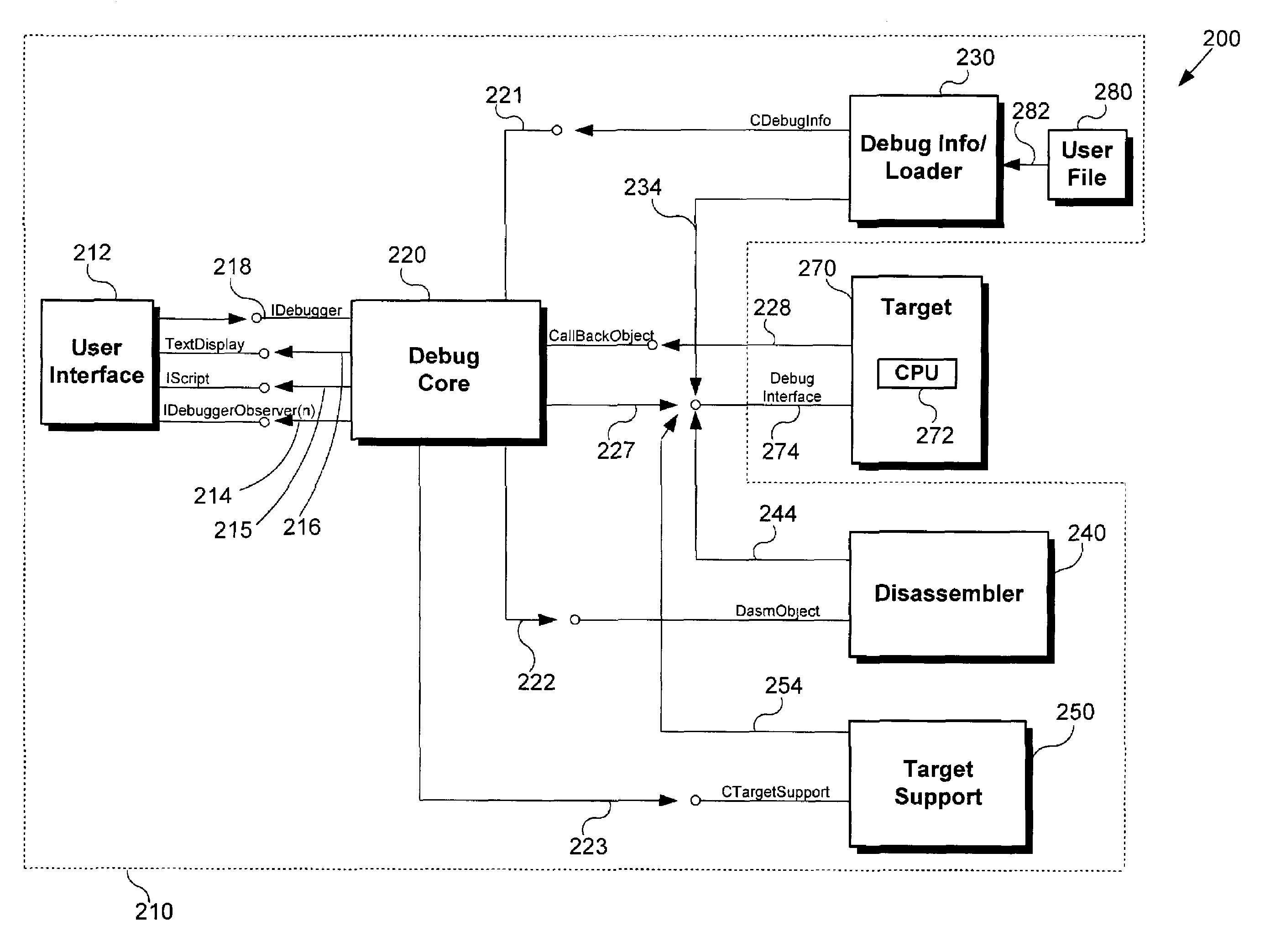
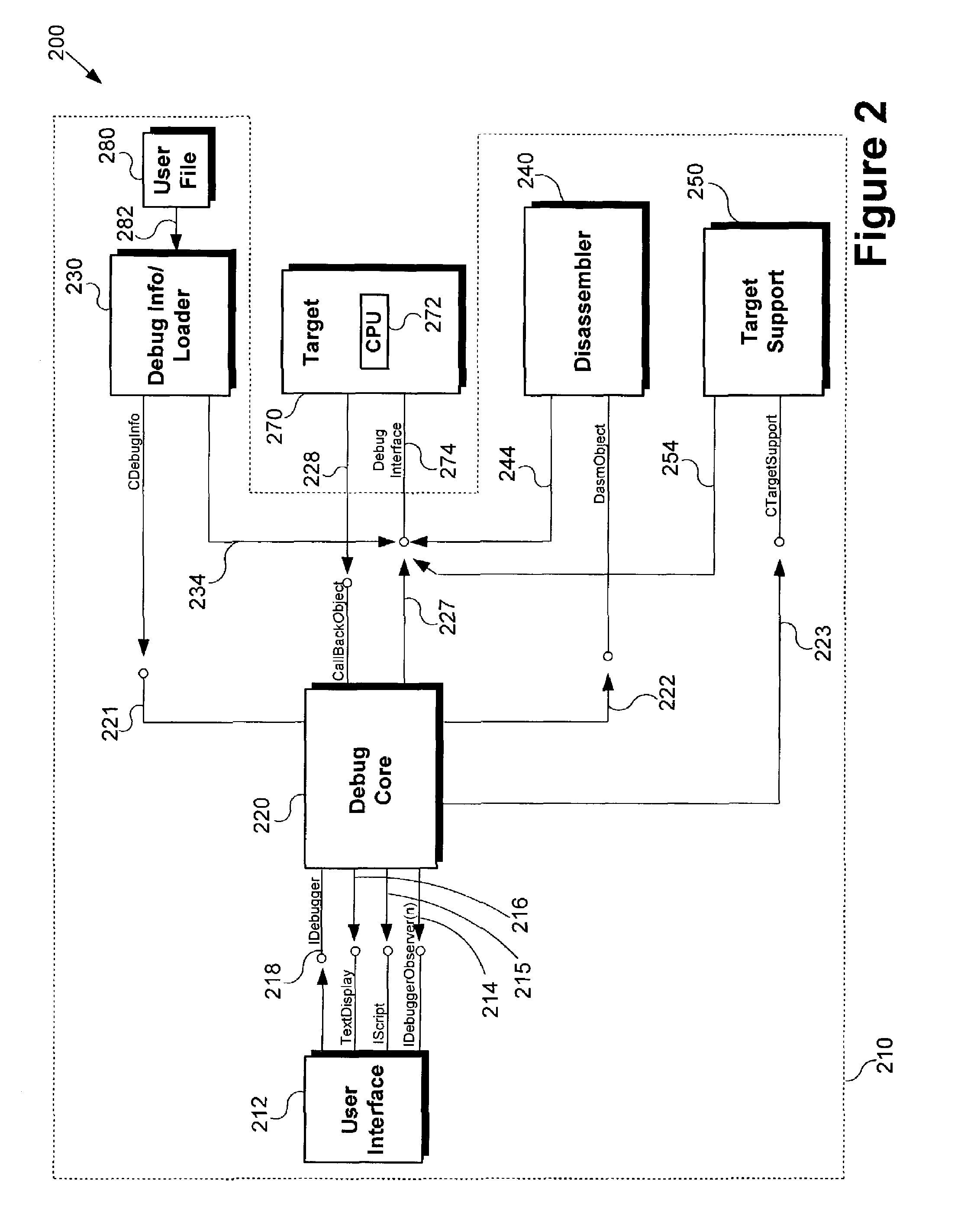
[0009]The present invention is directed to method and system for adapting a debugger to new targets. The present invention overcomes the need in the art for a debugging system that does not have to be rebuilt or customized in order to effectively and properly operate with different or new targets. In one embodiment, the invention is a method for adapting a debugger to a selected target. According to this embodiment, the debugger connects to the selected target through, for example, a debug interface. Thereafter a debug core in the debugger dynamically loads a module set from a target database that corresponds to the selected target. Next, a debug info / loader, a disassembler, and / or a target support are dynamically loaded based on the module set loaded by debug core. Thereafter, the debug info / loader, disassembler, and / or target support can directly connect to the selected target to retrieve additional target-specific information, such as target-specific memory, register, and file format information. By implementing the above method, the debugger can adapt to new or different targets, i.e. the debugger can be “retargeted,” without the need to rebuild different versions of the debugger to suit new or different targets.

Problems solved by technology

Currently, with the rapid changes in processor technologies, manufacturers of debuggers are continually forced to rebuild different versions of their debuggers to suit different processors, a practice that is both time consuming and technically laborious.

Method used


Image

  • Method and system for adapting a debugger to new targets
  • Method and system for adapting a debugger to new targets
  • Method and system for adapting a debugger to new targets

Examples


Embodiment Construction

[0015]The present invention is directed to method and system for adapting a debugger to new targets. The following description contains specific information pertaining to implementation of specific embodiments of the invention. However, one skilled in the art will recognize that the present invention may be implemented in a manner different from that specifically discussed in the present application. Moreover, some of the specific details, which are within the knowledge of a person of ordinary skill in the art, are not discussed to avoid obscuring the present invention.

[0016]The drawings in the present application and their accompanying detailed description are directed to merely exemplary embodiments of the invention. To maintain brevity, other embodiments of the invention which use the principles of the present invention are not specifically described in the present application and are not specifically illustrated by the present drawings.

[0017]An exemplary embodiment of a debuggin...


PUM


Abstract

One disclosed embodiment is a method for adapting a debugger to a selected target. According to this embodiment, the debugger connects to the selected target. Thereafter a debug core in the debugger dynamically loads a module set from a target database that corresponds to the selected target. Next, a debug info / loader, a disassembler, and / or a target support are dynamically loaded based on the module set loaded by debug core. Thereafter, the debug info / loader, disassembler, and / or target support can directly connect to the selected target to retrieve additional target-specific information. By implementing the above method, the debugger can adapt to new or different targets without the need to rebuild different versions of the debugger to suit new or different targets. In other embodiments, a system for implementing the above method, and a computer readable medium containing a computer program for implementing the above method, are disclosed.

Description

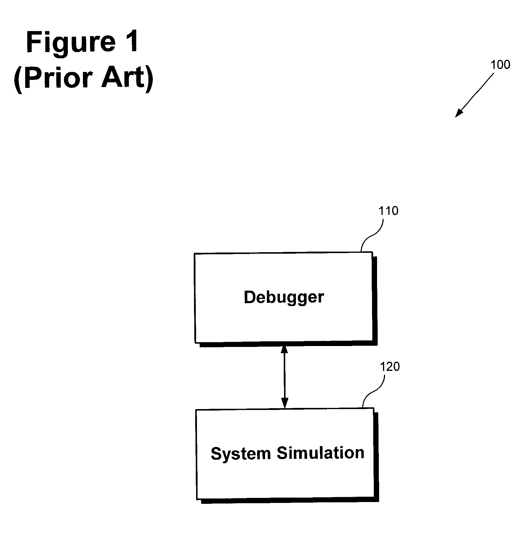
BACKGROUND OF THE INVENTION[0001]1. Field of the Invention[0002]The present invention is generally in the field of debuggers and, more particularly, in the field of debugger retargetability.[0003]2. Background Art[0004]Software for embedded systems is conventionally developed using a single microcontroller or a digital signal processor (DSP) and either an emulation or simulation module to which a debugger is attached. A debugger is a tool that aids a programmer or developer in locating and correcting errors in the system. In the case of a simulation module, the system and the debugger are both implemented in software.[0005]FIG. 1 illustrates a conventional exemplary single-processor system simulation, i.e. debugging system 100. In the present application, the entity upon which a debugger acts will be referred to as a “target” within a “system simulation.” A system simulation may include, for example, several targets, a scheduler, and a shared system resource such as a shared memory....

Claims


Application Information

Patent Timeline
IPC IPC(8): G06F11/00
CPCG06F11/362G06F11/3664
Inventor BEBOUT, DON W.SHAMABHAT, VARSHA T
Owner MACOM TECH SOLUTIONS HLDG INC
Learn More