Shroud plate attachment

a technology of shield plate and sleeve, which is applied in the direction of couplings, valve operating means/release devices, instruments, etc., to achieve the effect of giving rotational stability

Active Publication Date: 2005-09-06
NOROTOS
View PDF39 Cites 59 Cited by
  • Summary
  • Abstract
  • Description
  • Claims
  • Application Information

AI Technical Summary

Benefits of technology

[0009]The present invention provides for a shroud plate for headgear comprising a shell, an insert, a lock, a release mechanism wherein the shell extends around at least a portion of the insert has a smooth surface with rounded edges and corners and is shaped to match the contour of the headgear, and at least one attachment point wherein the attachment point is laterally movable within a restricted area. Further, the shroud plate may be attachable to headgear at a single attachment point and may be given rotational stability by an elevated ridge or a plurality of legs which may extend over or wrap around an edge of the headgear.

Problems solved by technology

It has been found, however, that the holes for the screws are not drilled in exactly the same locations on each helmet.
These and other issues exist with the helmet attachment mechanisms for night vision devices disclosed in the prior art.

Method used


Image

  • Shroud plate attachment
  • Shroud plate attachment
  • Shroud plate attachment

Examples


Embodiment Construction

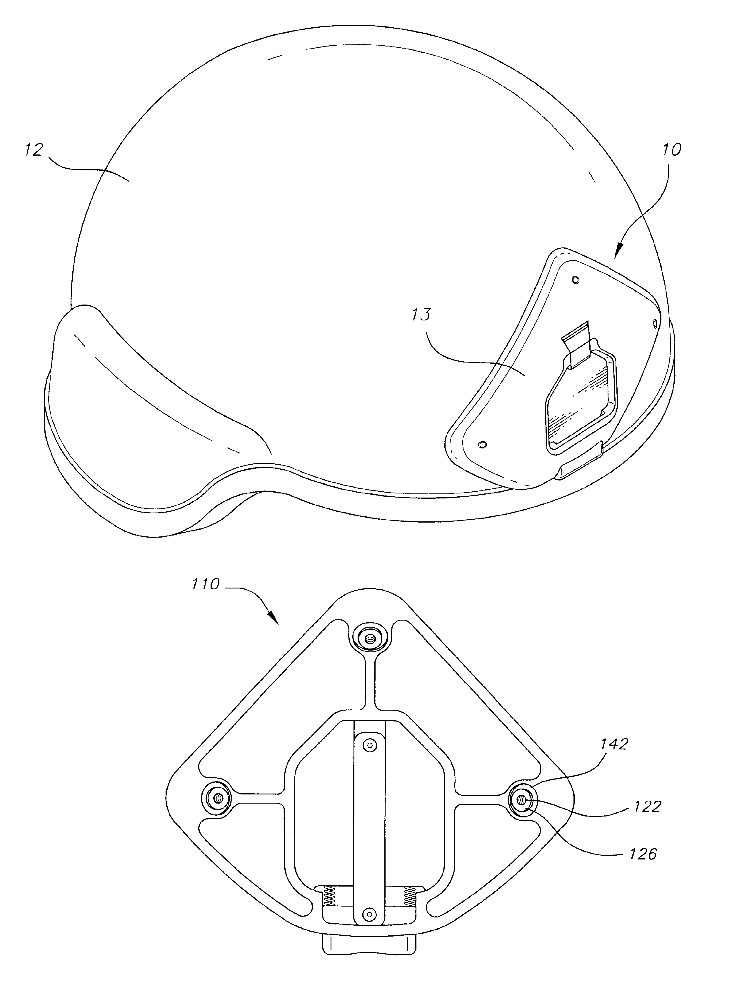
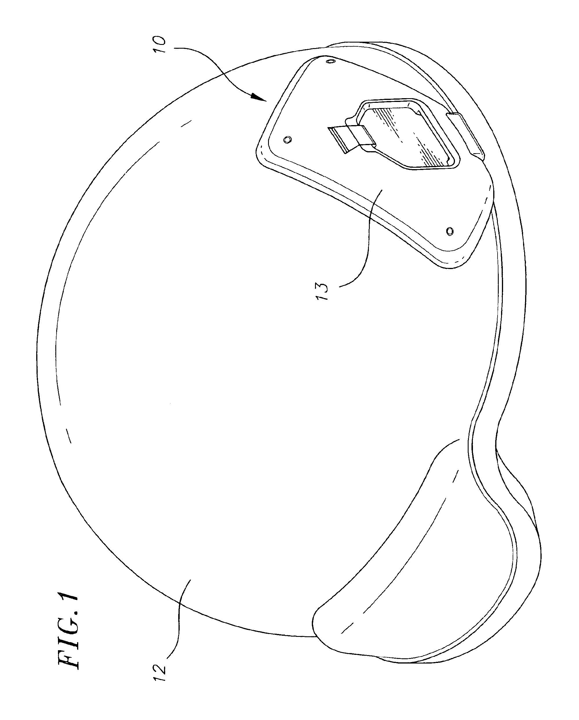
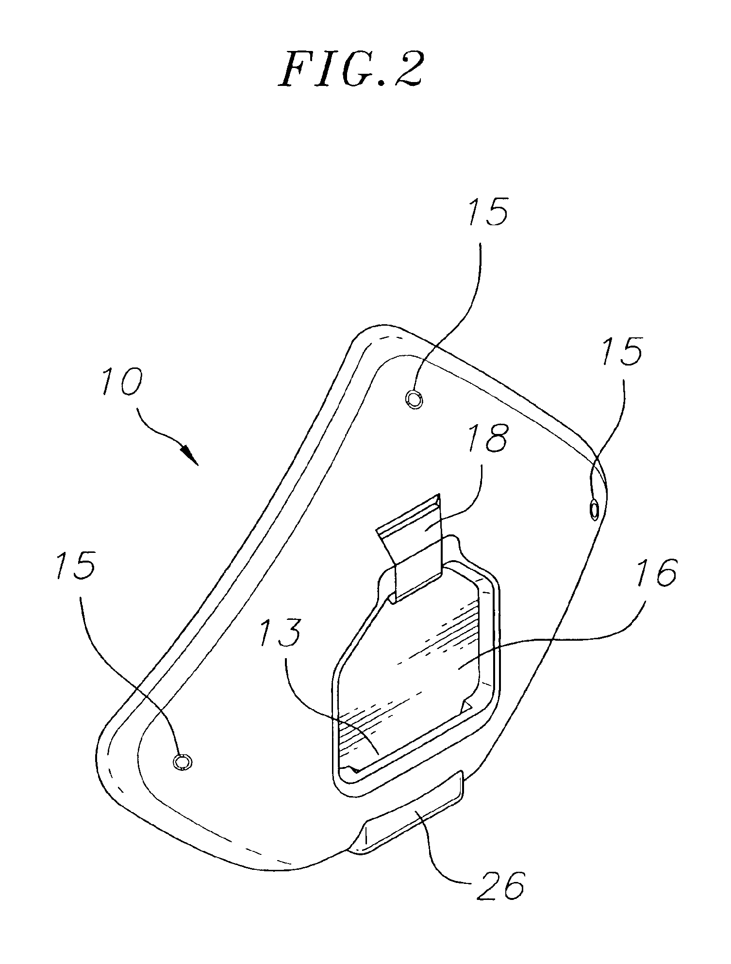
[0028]An exemplary embodiment of a shroud plate is shown in FIG. 1. The shroud plate 10 is shown attached to a standard U.S. Army Kevlar composite helmet 12. The helmet is based on U.S. Design Patent 449,411 to Largeot and is manufactured by CGF Helmets, Inc. of Akron, Ohio. In an exemplary embodiment, the shroud plate 10 may be attached to the helmet 12 by stainless steel screws 14 inserted into openings in the helmet 12 and shell 13. Flanged threaded inserts 15 may be driven into holes machined into shell 13. Threaded inserts 15 may also comprise a knurled outer surface in order to more securely attach them to the shell 13 when they are inserted into the machined hole. The threaded portion of the insert may also comprise two opposite halves attached to a flange at one end of the insert with a small gap separating the halves on their longitudinal axis. This separation allows the inserts to expand slightly when screws are threaded into them, tightly securing them to the shell 13. Ho...


PUM


Abstract

A shroud plate for headgear is provided that may comprise a shell, an insert, a lock, a release mechanism wherein the shell extends around at least a portion of the insert has a smooth surface with rounded edges and corners and is shaped to match the contour of the headgear, and at least one attachment point wherein the attachment point is laterally movable within a restricted area. Further, the shroud plate may be attachable to headgear at a single attachment point and may be given rotational stability by an elevated ridge or a plurality of legs which may extend over or wrap around an edge of the headgear.

Description

FIELD OF THE INVENTION[0001]This invention relates to helmet attachment mechanisms used with mounting assemblies for night vision devices, and more particularly to a shroud plate which may act as an interface between a helmet and the helmet mount for a night vision device.BACKGROUND OF THE INVENTION[0002]Night vision devices are commonly used by military personnel for conducting operations in low light or night conditions. The night vision devices used by the military typically include image intensifier tubes and associated optics that convert infrared and near infrared light into viewable images. A common night vision device currently being used in the U.S. Army is the PVS7 night vision goggle, manufactured by ITT Corporation of Roanoke, Va.[0003]Assemblies for mounting night vision devices to a helmet are well-known in the art. These mounting assemblies allow a user's hands to remain free while viewing a scene through the night vision device. It is also desirable for these mountin...

Claims


Application Information

Patent Timeline
Patent Type & Authority Patents(United States)
IPC IPC(8): A42B1/00A42B1/24A42B3/04E03C1/05F16B19/04F16B19/10F16K31/02G02B27/00G02B7/00G02B23/12
CPCA42B3/04G02B23/125Y10T403/75A42B3/0406A42B3/042
Inventor PRENDERGAST, JONATHON R.
Owner NOROTOS
Why Eureka
Try Eureka