Method to generate electrical current using a plurality of masses attached to piezoceramic supports

a technology of piezoceramic supports and masses, applied in the field of piezoelectric devices, to achieve the effect of maximizing the amount of energy each mems element generates

Inactive Publication Date: 2005-09-06
THE BOEING CO
View PDF23 Cites 33 Cited by
  • Summary
  • Abstract
  • Description
  • Claims
  • Application Information

AI Technical Summary

Benefits of technology

[0009]According to the principles of the present invention, large arrays of MEMS devices having weighted, cantilevered, piezoelectric beams in a bimorph configuration, oscillate and produce electrical current from vibrations of the surface to which they are attached. The piezoelectric power source of the present invention can be integrated in a variety of applications, including wireless sensor modules. The power devices of the present invention are capable of operation as part of a stand-alone unit that can last for the lifetime of a system, a time span measured in decades. The magnitude of energy needed for exemplary wireless sensor applications require a generation rate of milliwatts of power. This is achieved in the present invention by maximizing the amount of energy each MEMS element generates and by using a large array of elements.
[0010]The power source devices of the present invention are made of the following parts: (1) an element—a weighted, cantilevered MEMS piezoelectric bimorph beam; (2) a unit cell—a collection of MEMS elements in a form of about 1 centimeter squared (cm2) in area and about 0.5 millimeters (mm) thick, having about 150 to about 200 elements; (3) an array—the collection of many unit cells, typically about 100, all interconnected electrically to form a power generation unit; and (4) a protective sheath—a partially flexible electrically conductive material which forms a protective envelope for the unit cells on at least one element side and which provides the interconnection pathways between each element and the array. The sheath in one embodiment also provides a boundary limit, so that each piezobimorph element beam cannot overextend under impulse conditions, which could result in fracture. The sheath is preferably perforated, but can also be totally solid for some applications. The sheath is preferably flexible to permit an array to be connected over a flat or a contoured surface. The use of the sheath also allows for the array of MEMS piezoelectric bimorph beams to couple to longer wavelength harmonic vibrations of the structure, in a collective mode pattern, due the fact that all the elements of the array are mechanically joined to the sheath on one end.

Problems solved by technology

The sheath in one embodiment also provides a boundary limit, so that each piezobimorph element beam cannot overextend under impulse conditions, which could result in fracture.

Method used


Image

  • Method to generate electrical current using a plurality of masses attached to piezoceramic supports
  • Method to generate electrical current using a plurality of masses attached to piezoceramic supports
  • Method to generate electrical current using a plurality of masses attached to piezoceramic supports

Examples


Embodiment Construction

[0038]The following description of the preferred embodiments is merely exemplary in nature and is in no way intended to limit the invention, its application, or uses.

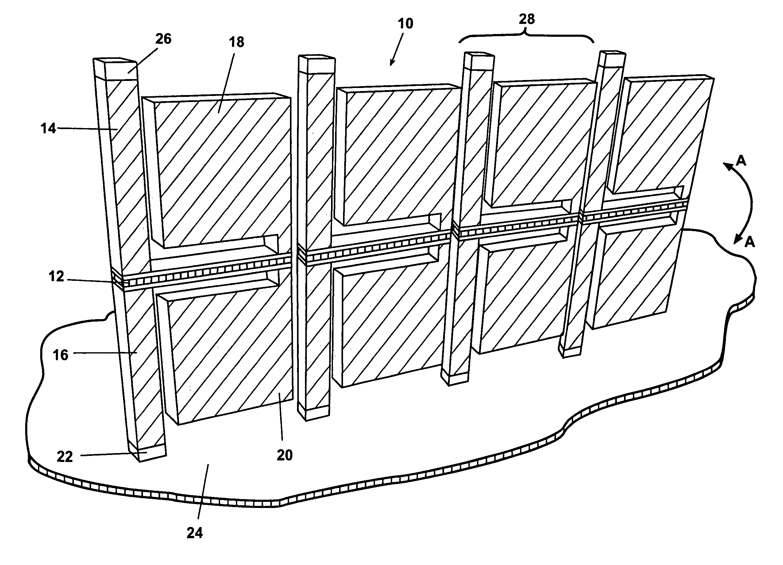
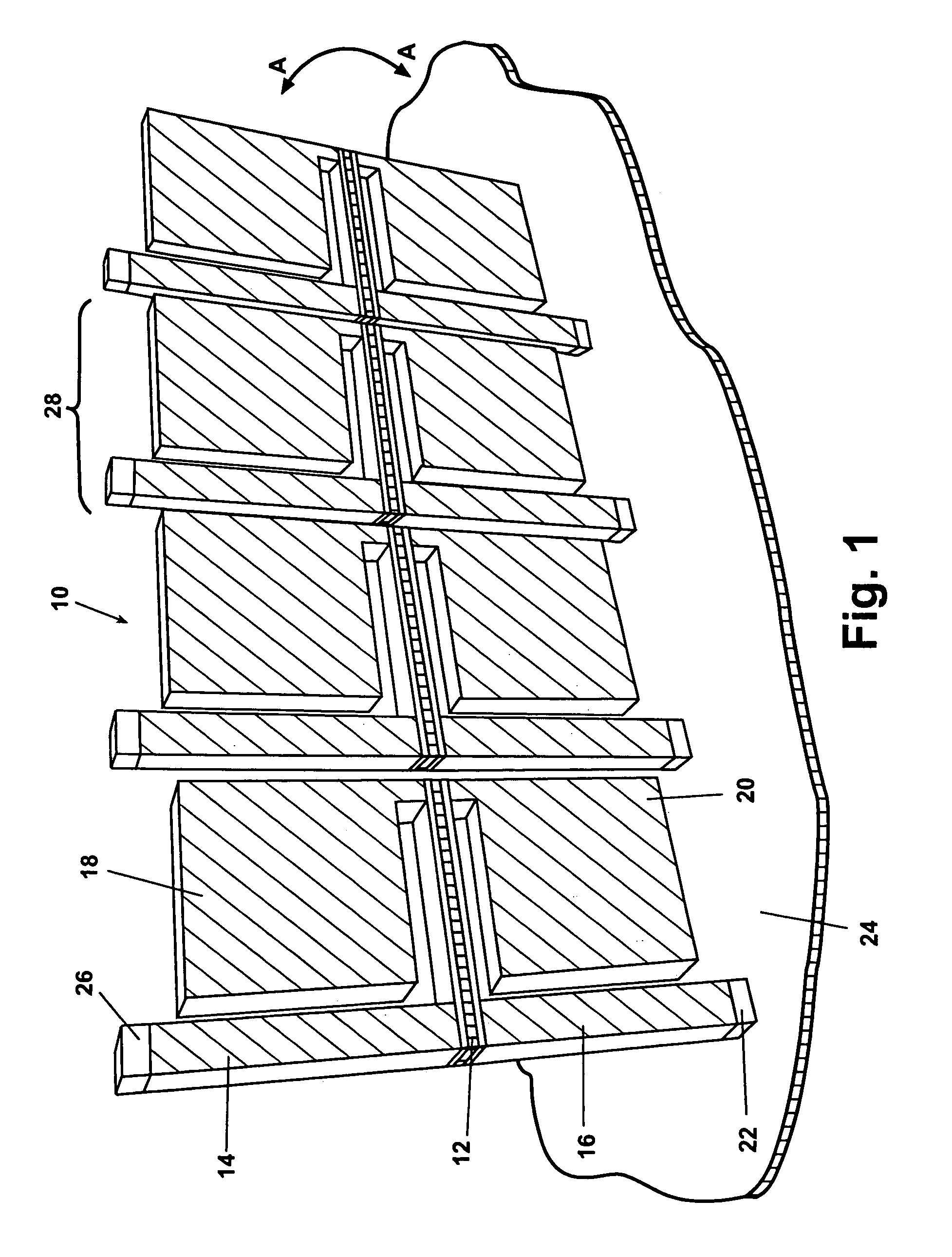
[0039]Referring to FIG. 1, a MEMS partial unit cell 10 is shown. Partial unit cell 10 comprises a plurality of piezoelectric cantilevered beams 12. At a fixed or support end of each of the piezoelectric cantilevered beams 12, an intermediate upper column 14 and an intermediate lower column 16 are provided. At a distal end of each piezoelectric cantilevered beam 12, an upper cantilevered mass 18 and a lower cantilevered mass 20 are provided. The upper and lower cantilevered masses 18 and 20, respectively, are provided to lower the resonant mode of the relatively short and stiff piezoelectric cantilevered beam 12.

[0040]When attached to a vibrating structure or item, the partial unit cell 10 will vibrate in response to the vibration source. The upper cantilevered mass 18 and the lower cantilevered mass 20 will deflect in t...


PUM

PropertyMeasurementUnit
thickaaaaaaaaaa
thickaaaaaaaaaa
thicknessaaaaaaaaaa

Abstract

A method is provided to generate electrical current. The method includes creating a plurality of unitary masses each connected to one of a plurality of piezoceramic mass supports. The mass supports are electrically joined to a sheath. The method also includes removing material from the unitary masses to operably limit a mass vibration deflection. The sheath is attached to a vibrating body. The unitary masses are pre-tuned to match at least one natural frequency mode of the vibrating body. The unitary masses and the piezoceramic mass supports are induced to vibrate to generate the electrical current.

Description

CROSS-REFERENCE TO RELATED APPLICATIONS[0001]This application is a divisional of U.S. patent application Ser. No. 10 / 124,049 filed on Apr. 17, 2002 now U.S. Pat. No. 6,771,007, the disclosure of which is incorporated herein by reference.FIELD OF THE INVENTION[0002]The present invention relates generally to piezoelectric devices which generate electrical energy by induced vibration and more specifically to an apparatus and method to utilize a thin, conformable sheet, having a plurality of piezobimorph cantilevered beams to produce electrical energy.BACKGROUND OF THE INVENTION[0003]Moving objects or platforms generate vibration energy which is commonly steady in amplitude or that increases with age of the object or platform. All platforms suffer material degradation over time due to this continuous vibration, and for this reason system inspections are periodically performed or sensors are installed to monitor strain levels in such structures to help predict material failure. Common re...

Claims


Application Information

Patent Timeline
Patent Type & Authority Patents(United States)
IPC IPC(8): H01L41/113H01L41/24
CPCH01L41/1136H01L41/257H02N2/186Y10T29/49128Y10T29/49126Y10T29/49798Y10T29/49149Y10T29/42Y10T29/49004H10N30/306H10N30/01
Inventor TANIELIAN, MINAS H.
Owner THE BOEING CO
Why Eureka
Try Eureka