High intensity focused ultrasound with capacitive micromachined transducers

a micro-machined, ultrasonic technology, applied in the field of high intensity focused ultrasound, can solve the problems of limiting the design of the catheter transducer to one-dimensional phased arrays, limiting the possible sonication methods that can be used, and reducing the space available for the transducer. , to achieve the effect of greater control of sonication and more accurate or effective sonication

Active Publication Date: 2015-03-05
KONINKLIJKE PHILIPS ELECTRONICS NV
View PDF4 Cites 10 Cited by
  • Summary
  • Abstract
  • Description
  • Claims
  • Application Information

AI Technical Summary

Benefits of technology

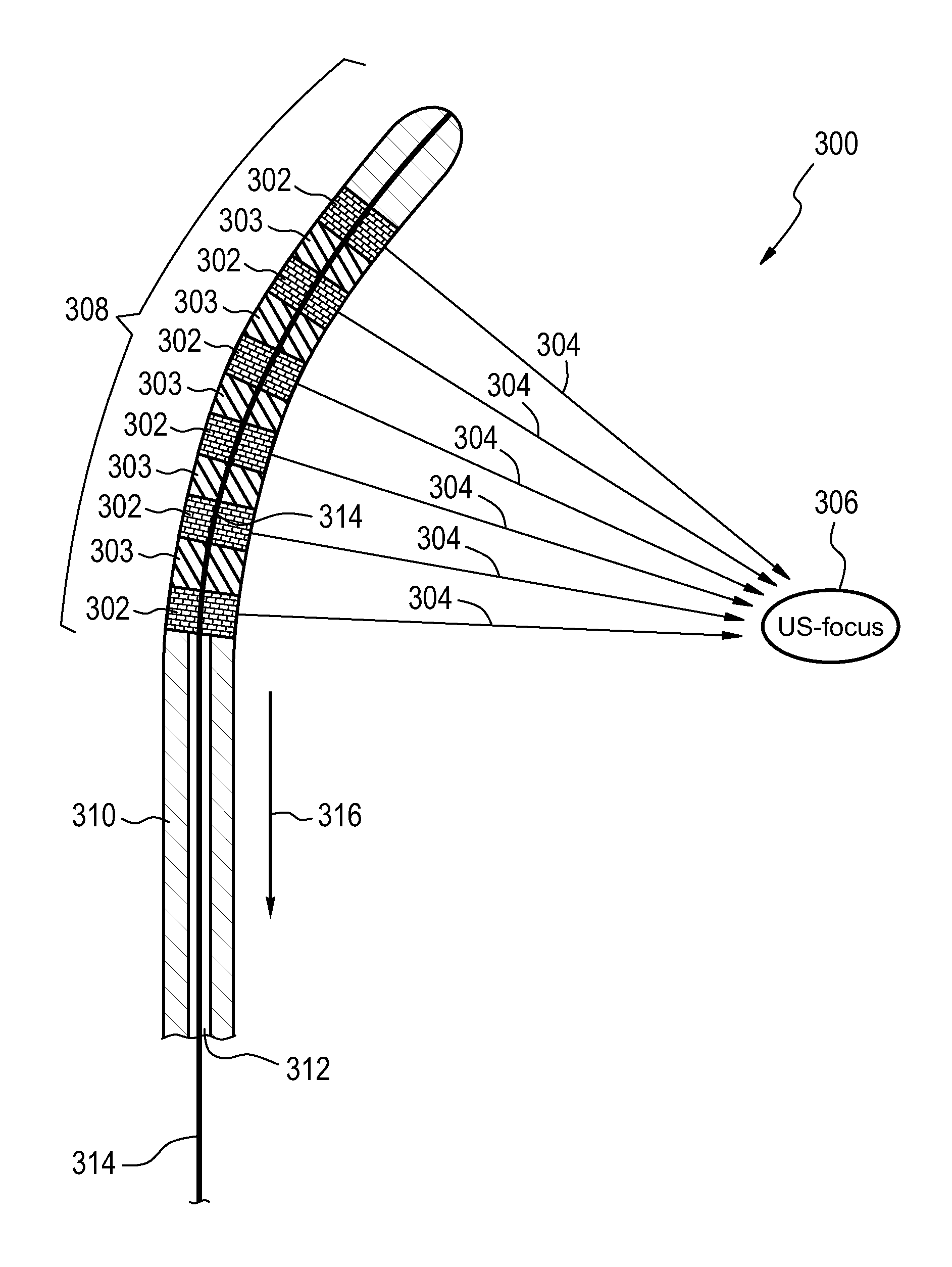
[0029]In another embodiment the medical instrument further comprises a catheter. The catheter comprises the ultrasound transducer. This embodiment may be beneficial because the capacitive micromachined ultrasound transducers are small enough that they may be placed on a catheter. This may enable a catheter which may have electronic steering of the sonications which also has an adjustable sonication frequency.
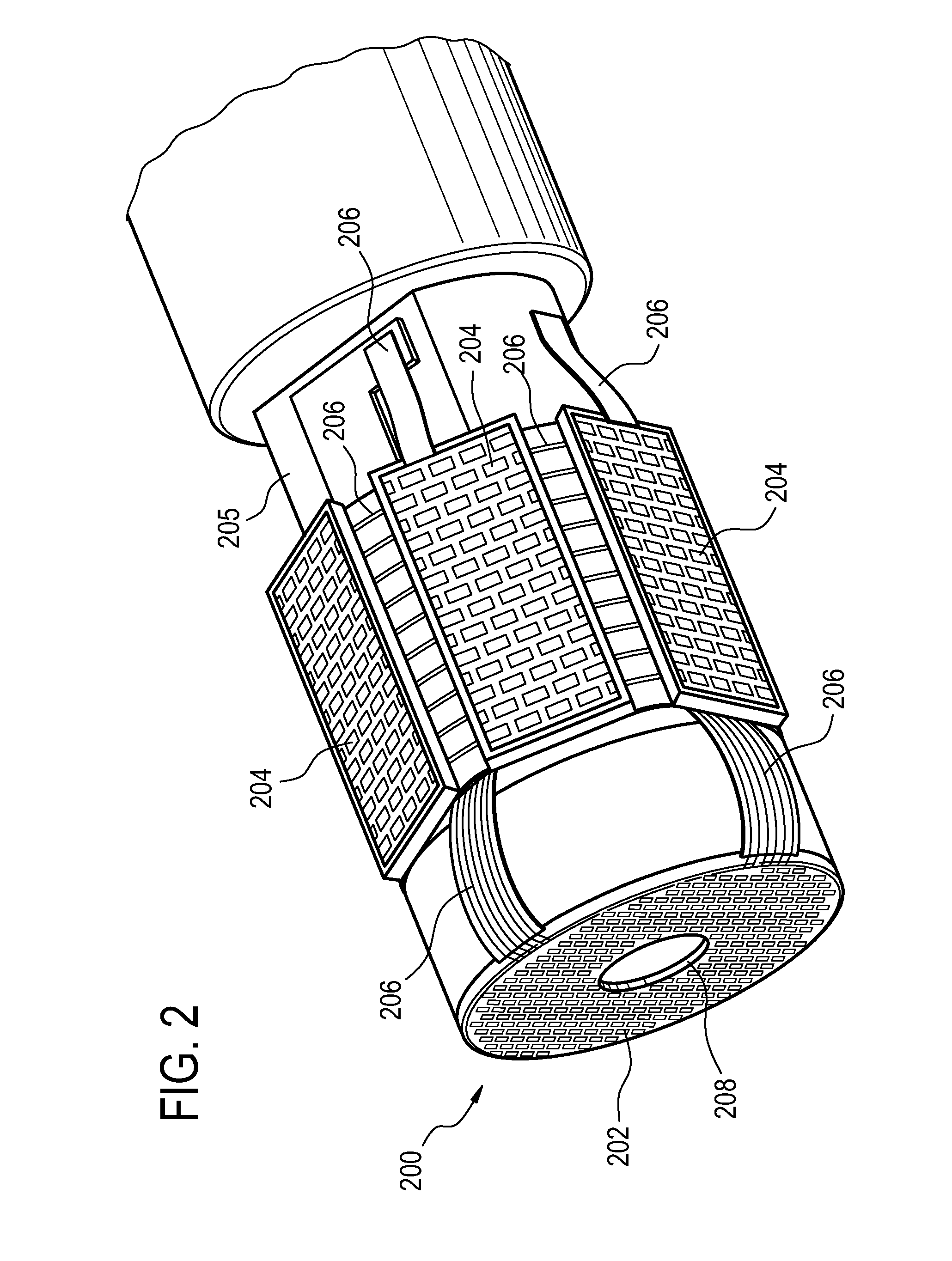
[0030]In another embodiment the catheter further comprises a shaft with a distal end and a proximal end. The distal end comprises the first capacitive micromachined ultrasound transducer array and the second capacitive micromachined ultrasound transducer array. The catheter further comprises a connector at the proximal end for supplying the first capacitive micromachined ultrasound transducer array and the second capacitive micromachined ultrasound transducer array with electrical power and for controlling the first sonication frequency and the second sonication frequency. This embodiment may be beneficial because it provides for a catheter which has different arrays of capacitive micromachined ultrasound transducers which can be independently controlled. This may result in more accurate or effective sonication.
[0031]In another embodiment the first capacitive micromachined ultrasound transducer array has a first adjustable focus and the second capacitive micromachined ultrasound transducer array has a second adjustable focus. An adjustable focus as used herein encompasses electronic control of the focus. There are multiple individual arrays. The phase and/or amplitude may be controlled individually for each of the individual capacitive micromachined ...

Problems solved by technology

The main disadvantage of the transurethral approach is that the space available for the transducer is substantially reduced as compared to the transrectal approach.
This basically limits the c...

Method used


Image

  • High intensity focused ultrasound with capacitive micromachined transducers
  • High intensity focused ultrasound with capacitive micromachined transducers
  • High intensity focused ultrasound with capacitive micromachined transducers

Examples


Embodiment Construction

[0048]Like numbered elements in these figures are either equivalent elements or perform the same function. Elements which have been discussed previously will not necessarily be discussed in later figures if the function is equivalent.

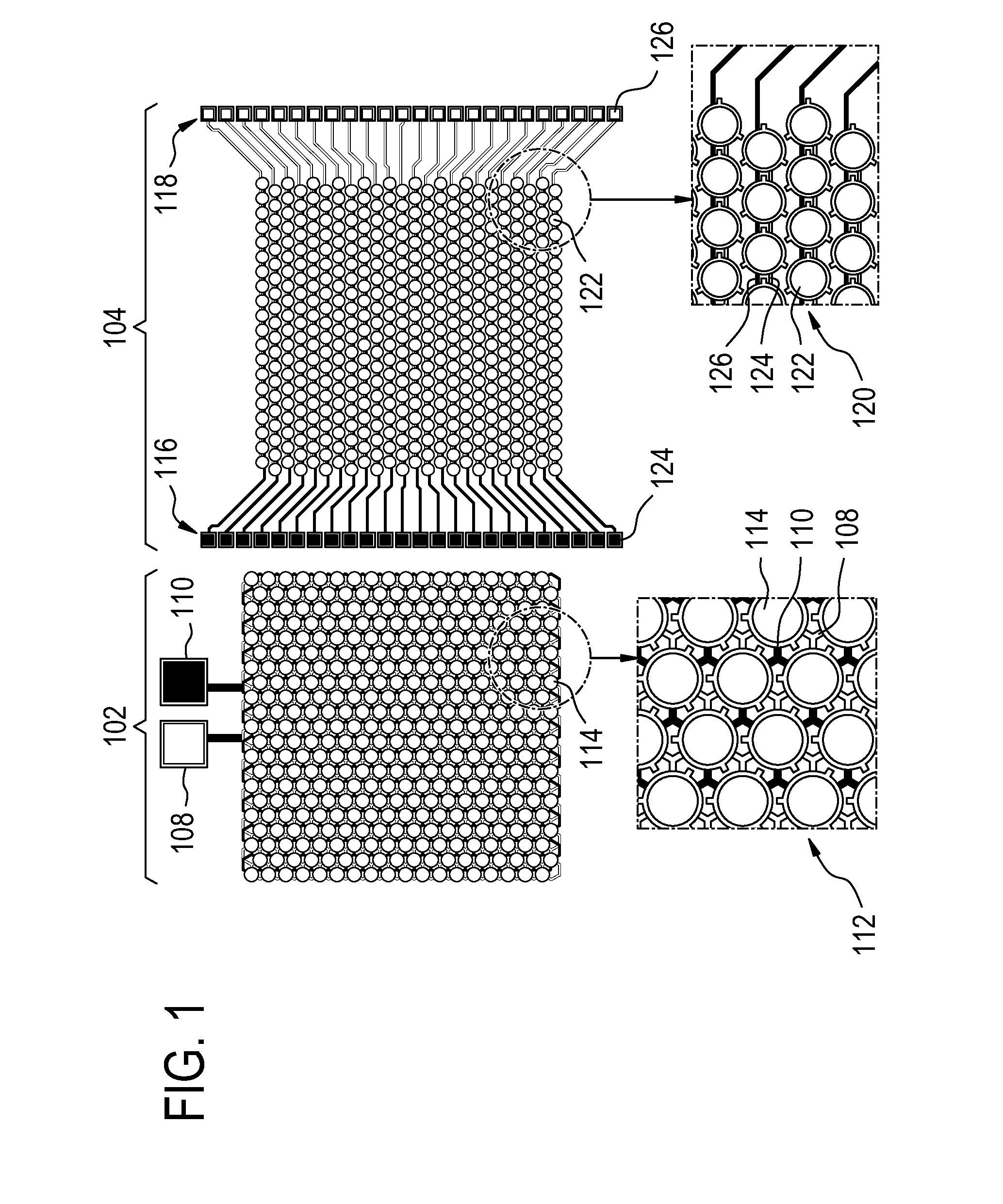
[0049]In FIG. 1 two examples of arrays 402, 404 of capacitive micromachined ultrasound transducers are shown. The capacitive micromachined ultrasound transducer array 102 has first 108 and second 110 electrical connections. Array 102 is wired so that it functions as a single transducer element in the way that a traditional piezoelectric element does. Drawing 112 shows a blowup of array 102. The individual capacitive micromachined ultrasound transducers 114 can be seen. It can be seen that each of the transducers 114 is connected to the first 108 and second 110 electrical connections. In this example the resulting array 102 would have a wide bandwidth for the sonication frequency, however individual electronic, phase and amplitude, control of the individ...


PUM


Abstract

A medical instrument (900, 1000) comprising a high intensity focused ultrasound system (911) comprising an ultrasound transducer (102, 104, 202, 204, 302, 407, 08) with an adjustable sonication frequency. The ultrasound transducer comprises capacitive micromachined transducers (102, 104, 202, 204, 302, 407, 508). Execution of machine executable instructions by a processor causes the processor to: receive (700, 800) a treatment plan (924) descriptive of a target zone (908) within a subject (902); determine (702, 802) a traversal distance (926) through the subject to the target zone using the treatment plan, wherein the traversal distance is descriptive of the traversal of ultrasound from the ultrasound transducer to the target zone; determine (704, 804) a sonication frequency (829) using the traversal distance for focusing the sonication volume onto the target zone; and sonicate (706, 806) the target zone using the high intensity focused ultrasound system at the sonication frequency.

Description

TECHNICAL FIELD[0001]The invention relates to high intensity focused ultrasound, in particular to the use of capacitive micromachined ultrasound transducers for high intensity focused ultrasound.BACKGROUND OF THE INVENTION[0002]High-intensity focused ultrasound (HIFU) ablation of the prostate has conventionally been done through the rectal wall with a transrectal probe. Alternatively, ablation can also be done through the wall of the urethra using a transurethral probe. The transurethral approach has several safety-related advantages as compared to the transrectal approach. Because the location of the urethra is known (probe within urethra), it is easier to avoid unintentional thermal damage to the urethra that might increase the risk of incontinency. Moreover, since there is no sonication through the rectal wall, the risk of damaging this sensitive structure is also significantly reduced. The main disadvantage of the transurethral approach is that the space available for the transd...

Claims


Application Information

Patent Timeline
IPC IPC(8): A61N7/00
CPCA61N2007/0004A61N7/00A61N7/02A61N2007/0043A61N2007/0078A61N2007/0086A61N2007/0073
Inventor KOHLER, MAX OSKAR
Owner KONINKLIJKE PHILIPS ELECTRONICS NV
Why Eureka
Try Eureka