Method of manufacturing stator coil of rotary electric machine

a technology of rotary electric machines and stator coils, which is applied in the manufacture of stator/rotor bodies, magnets, magnetic bodies, etc., can solve the problems of complex process for manufacturing stator coils, and achieve the effect of improving and simplifying the method of manufacturing

Inactive Publication Date: 2005-09-06
DENSO CORP
View PDF9 Cites 18 Cited by
  • Summary
  • Abstract
  • Description
  • Claims
  • Application Information

AI Technical Summary

Benefits of technology

[0011]The present invention has been made in view of the above-mentioned problem, and an object of the present invention is to provide an improved and simplified method of manufacturing a stator coil of a rotary electric machine.

Problems solved by technology

Accordingly, the process for manufacturing the stator coil has not been simple.

Method used


Image

  • Method of manufacturing stator coil of rotary electric machine
  • Method of manufacturing stator coil of rotary electric machine
  • Method of manufacturing stator coil of rotary electric machine

Examples


Embodiment Construction

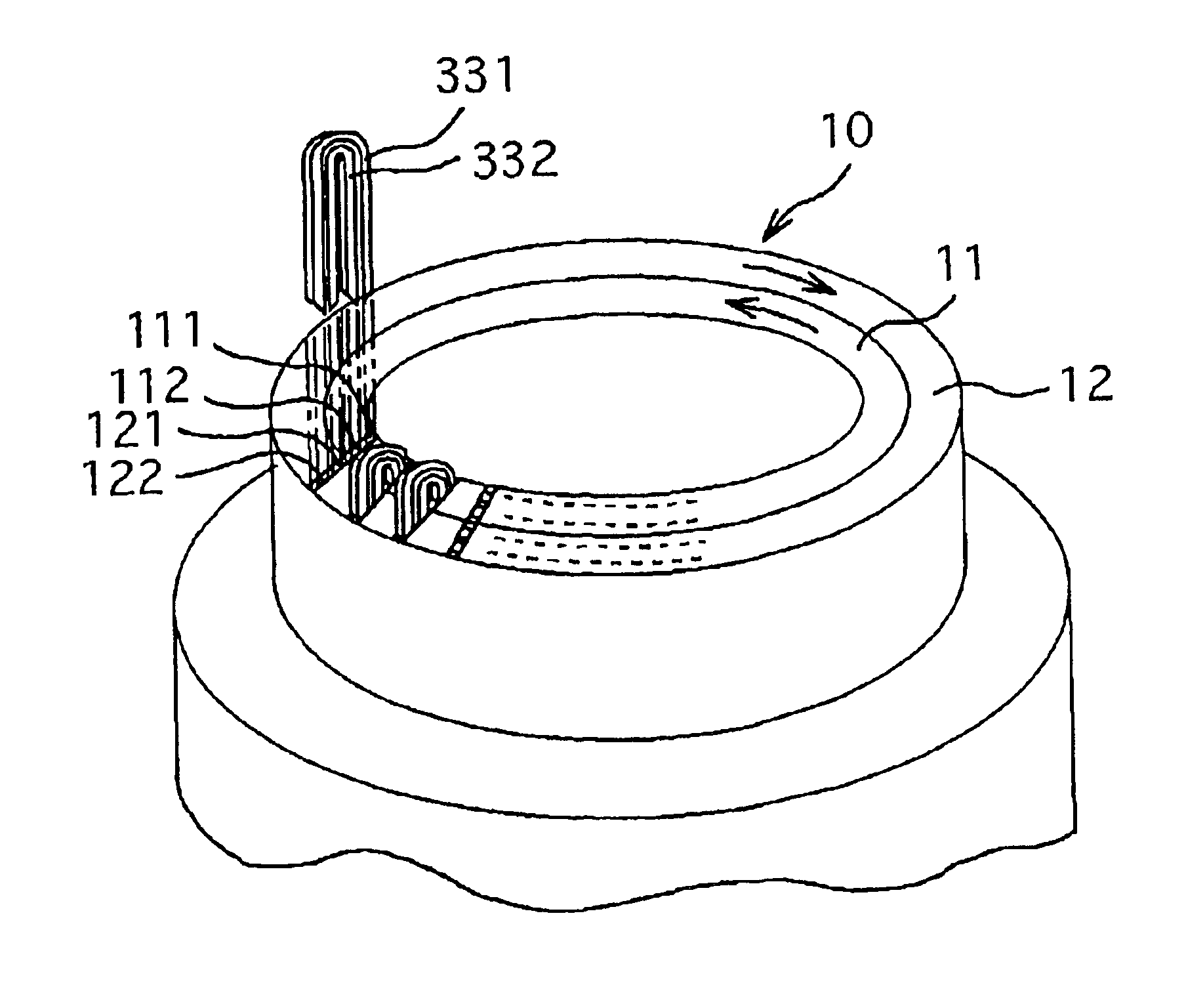
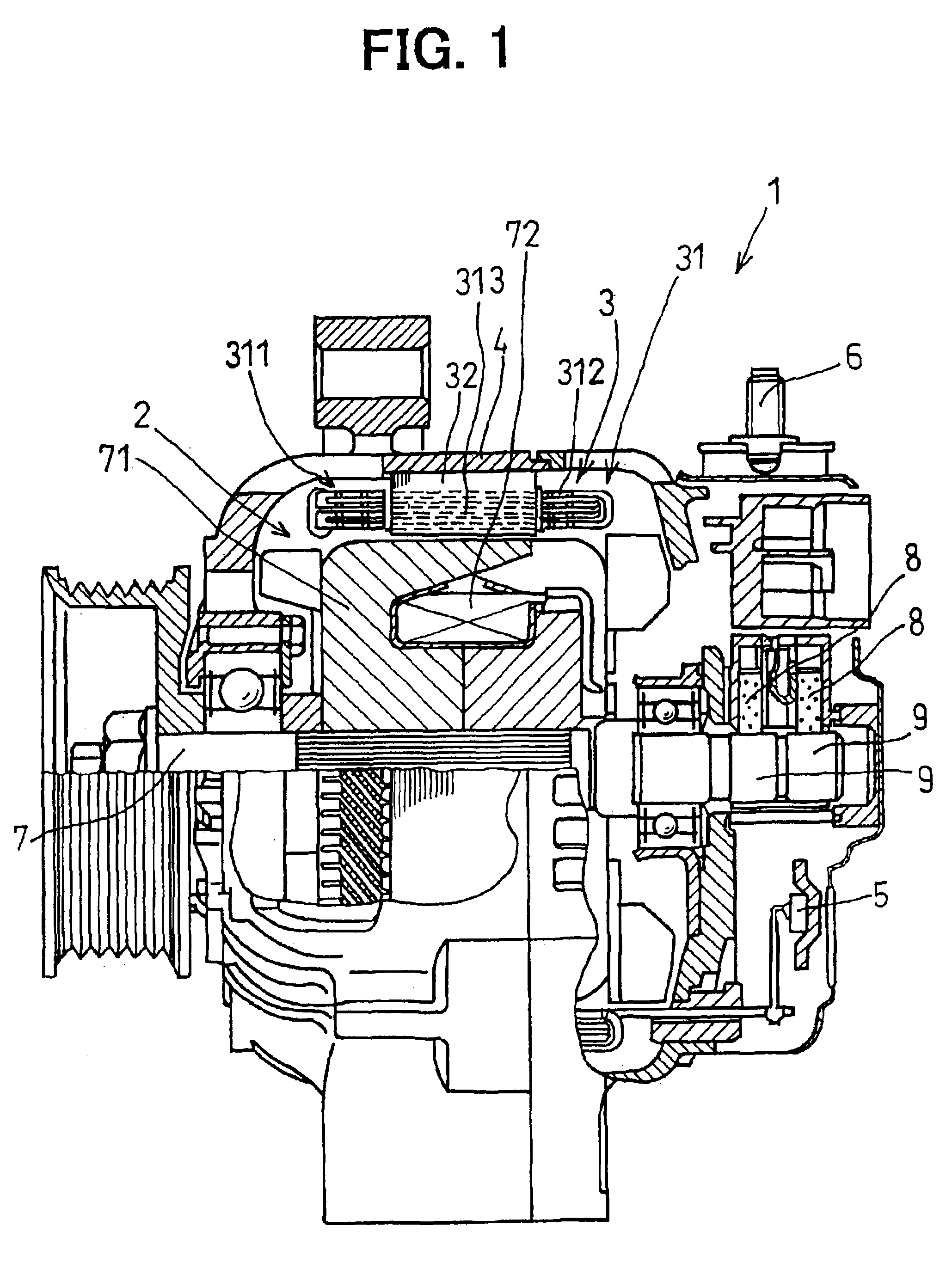
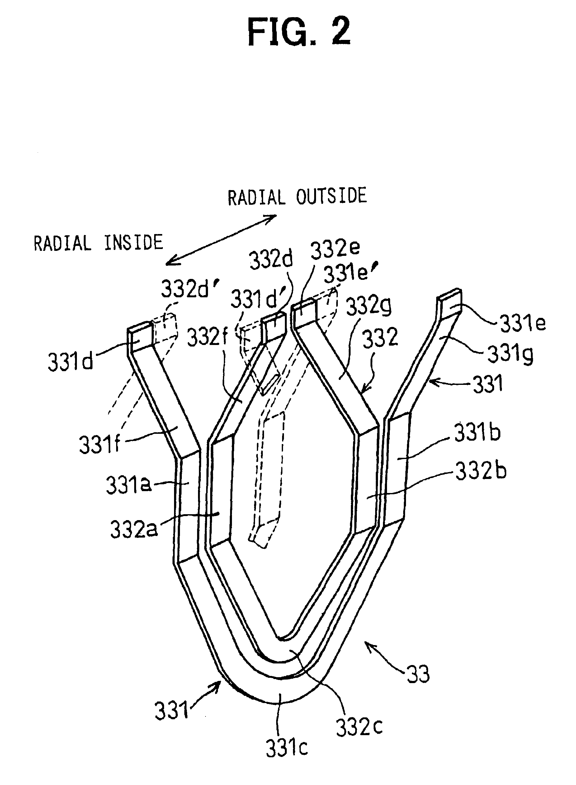
[0037]A preferred embodiment of the present invention will be described with reference to accompanying drawings. First, referring to FIG. 1, an entire structure of an alternator for use in an automotive vehicle will be described. The alternator 1 is composed of a rotor 2, a stator 3, a housing 4, a rectifier 5, an output terminal 6, a rotor shaft 7, brushes 8, slip rings 9 and other associated components. The stator 3 is composed of a stator core 32 having plural slots formed therein and a stator coil 31 disposed in the slots. The stator core 32 is fixedly supported inside the housing 4. The rotor 2 is composed of a pair of rotor cores 71 fixedly connected to the rotor shaft 7 and a field coil 72 wound on the rotor cores 71. The rotor shaft 7 is rotatably supported in the housing 4, and the rotor 2 is disposed inside the stator 3.

[0038]The stator coil 31 is a three-phase armature winding having three terminals for outputting three-phase alternating current. The three-phase alternati...


PUM

PropertyMeasurementUnit
rotational angleaaaaaaaaaa
electric angleaaaaaaaaaa
distanceaaaaaaaaaa

Abstract

A stator coil of a rotary electric machine such as an alternator for use in an automobile is composed of a plurality of U-shaped conductor segments inserted into slots formed in a stator core. Each segment has a head portion and two legs extending from the head portion. The plurality of segments include regular segments each having a regular distance between two legs (a regular slot-pitch) and special segments each having a special slot-pitch different from the regular slot-pitch. The head portions of both the regular and the special segments are simultaneously twisted to form the respectively required slot-pitches after a preliminary twist is given to the special segments. In this manner, a process of manufacturing the stator coil is simplified.

Description

CROSS-REFERENCE TO RELATED APPLICATION[0001]This application is based upon and claims benefit of priority of Japanese Patent Application No. 2001-397259 filed on Dec. 27, 2001, the content of which is incorporated herein by reference.BACKGROUND OF THE INVENTION[0002]1. Field of the Invention[0003]The present invention relates to a method of manufacturing a stator coil of a rotary electric machine such as an alternator for use in an automotive vehicle.[0004]2. Description of Related Art[0005]A method of manufacturing a stator coil for a rotary electric machine is disclosed, for example, in JP-B2-3118837 and JP-B2-3196738. The stator coil disclosed in these patents has a plurality of U-shaped conductor segments inserted into stator slots in its axial direction. Leg-end portions of the U-shaped conductor segments are electrically connected to one another after the segments are inserted into the stator slots, thereby forming a stator coil. The U-shaped conductor segment has a head porti...

Claims


Application Information

Patent Timeline
Patent Type & Authority Patents(United States)
IPC IPC(8): H02K15/00H02K15/04H02K3/04
CPCH02K15/0037H02K15/0414H02K15/0428Y10T29/49011Y10T29/49009Y10T29/49012Y10T29/53143Y10T29/49071H02K3/14
Inventor KATOU, MITSURUKITAKADO, YASUNORIMURAHASHI, MOTOHIRO
Owner DENSO CORP
Why Eureka
Try Eureka