Cooling system

a cooling system and cooling system technology, applied in the field of heat transfer apparatus, can solve the problems of reducing the comfort of occupants, the inability to use circulating cooled water to cool the air within the structure in residential applications, and the inability to meet the needs of occupants,

Inactive Publication Date: 2005-09-06
CONSOLI ART
View PDF13 Cites 71 Cited by
  • Summary
  • Abstract
  • Description
  • Claims
  • Application Information

AI Technical Summary

Problems solved by technology

Such evaporative systems, however, tend to humidify the air within the structure, causing reduced occupant comfort after a certain dew point is reached.
The residential use of circulating cooled water to cool the air within a st

Method used


Image

  • Cooling system
  • Cooling system
  • Cooling system

Examples


Embodiment Construction

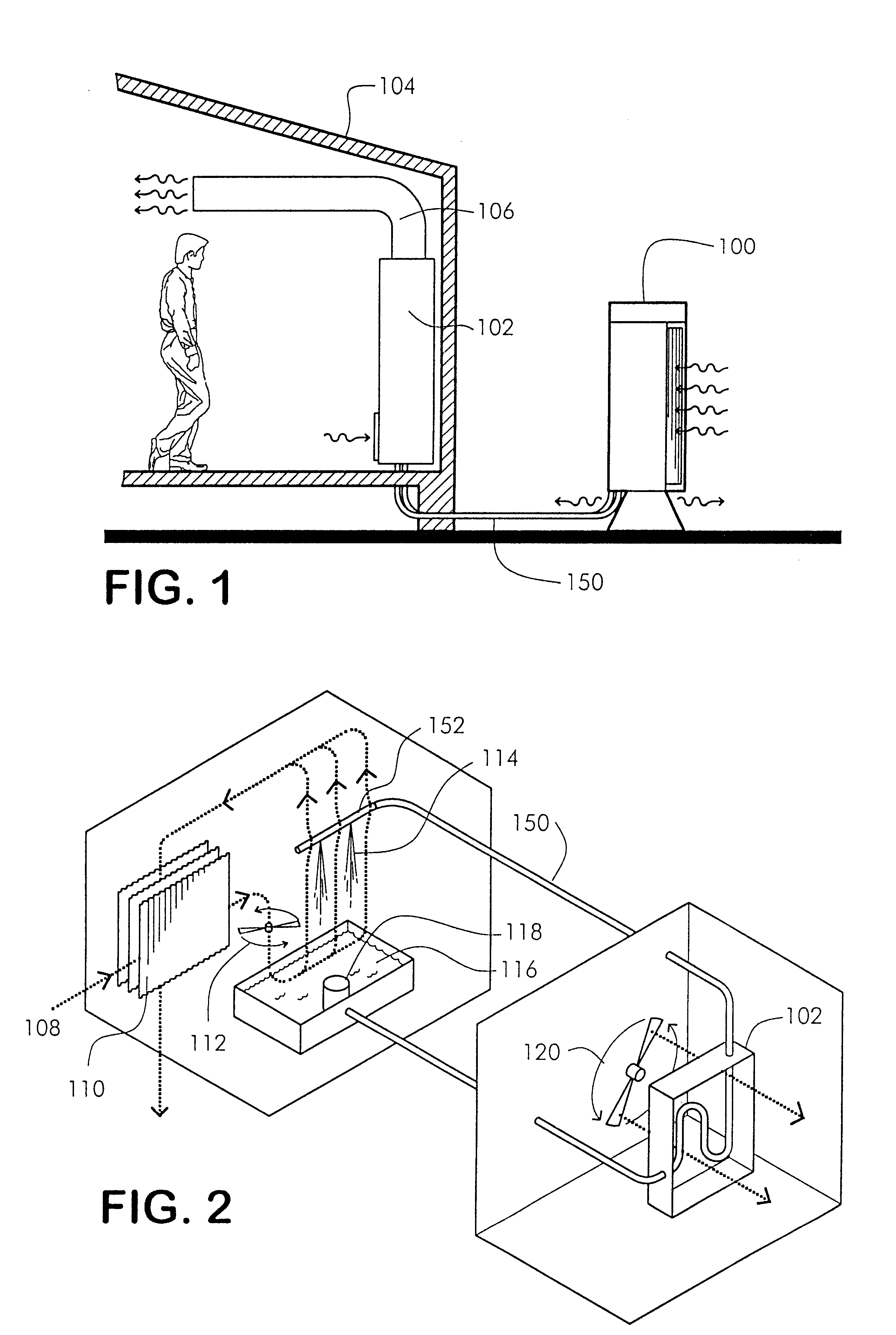
[0027]Reference is now made to the drawings. FIG. 1 is a perspective view of the cooling system 100, according to a preferred embodiment of the present invention. Illustrated is a cooling system 100 used to generate a cooled liquid coolant that is delivered through at least one liquid coolant transfer system 150, to at least one structure heat exchanger 102, for cooling the air inside the interior of a habitable structure 104 through one or more air ducts 106, as shown.

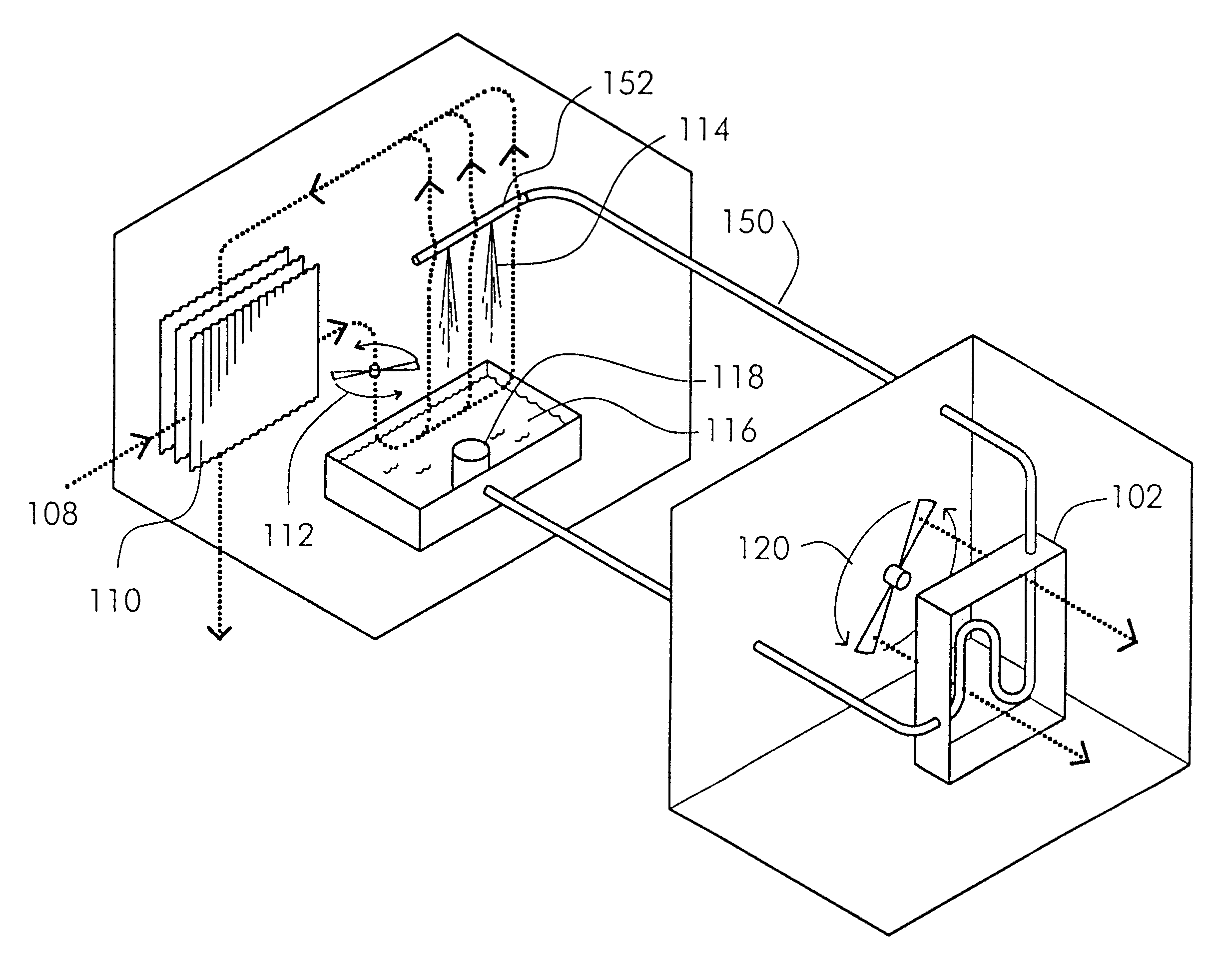
[0028]FIG. 2 is a diagrammatic view of air and liquid coolant through a preferred embodiment of the present invention. Preferably, the intake air 108 is drawn horizontally through at least one heat exchanger 110 by at least one blower 112 (embodying herein at least one air mover), as shown. Preferably, the air stream (embodying herein at least one first stream of air) is then forced up through at least one liquid coolant spray 114 (embodying herein at least one sprayer), and exhausted, vertically downward, through at ...


PUM

PropertyMeasurementUnit
Temperatureaaaaaaaaaa
Sizeaaaaaaaaaa
Electrical conductoraaaaaaaaaa

Abstract

A system is disclosed that incorporates a generator for generating a liquid coolant. This invention provides a self-contained water (or similar liquid coolant) chilling system of suitable capacity to cool small to medium size structures, such as private residences and manufactured homes. The system utilizes an arrangement of heat-exchanging panels to pre-condition an ambient temperature air-stream, prior to passage through a pump-driven coolant spray. The system also provides several sub-systems for automatic coolant monitoring, chemical addition and periodic coolant replacement.

Description

CROSS-REFERENCE TO RELATED APPLICATIONS[0001]This application claims the benefit of Provisional Application Serial No. 60 / 352,694, filed Jan. 28, 2002.FIELD OF THE INVENTION[0002]This invention relates to heat transfer apparatus and methods for providing conditioned air to habitable structures.BACKGROUND OF THE INVENTION[0003]Typically, cooling systems, such as those used for cooling structures, such as buildings and trailers, consist of systems that cool the air. The air-cooling is performed in many ways, such as using cooled refrigerant, cooled air or cooled water. Evaporative cooling systems have historically been less expensive than refrigerant systems. Evaporative systems that utilize the evaporation of water, such as those that use pads soaked with water and have air drawn through them, have been in use for many years. Such evaporative systems, however, tend to humidify the air within the structure, causing reduced occupant comfort after a certain dew point is reached.[0004]Th...

Claims


Application Information

Patent Timeline
IPC IPC(8): F25D17/00F24F5/00
CPCF24F5/0035Y02B30/545Y02B30/54
Inventor FAIR, SHIELDS
Owner CONSOLI ART
Why Eureka
Try Eureka