Vortex flow pickup

a pickup and flow technology, applied in the field of vortex flow pickup, can solve the problem of not being resistant to all fluids, and achieve the effect of good heat conductors and precise temperature measuremen

Inactive Publication Date: 2005-09-06
ENDRESS HAUSER FLOWTEC AG
View PDF16 Cites 51 Cited by
  • Summary
  • Abstract
  • Description
  • Claims
  • Application Information

AI Technical Summary

Benefits of technology

[0060]One advantage of the invention is that the temperature sensor has no chance of coming into contact with the flowing fluid and consequently also cannot be corroded by it. Nevertheless, the temperature sensor is arranged so close to the fluid that it senses its temperature with virtually no delay; it is in fact separated from the fluid only by the thin wall of the vortex sensor or of the bluff body and, like the remaining parts of the vortex flow pickup, these parts are produced from a metal, preferably stainless steel, and are therefore good heat conductors.
[0061]A further advantage of the invention is that, in a way corresponding to the book by F. P. Incropera and D. P, DeWitt “Fundamentals of Heat and Mass Transfer”, 4th edition, 1996, ISBN 0-471-30460-3, pages 114 to 119 and 407, the temperature sensor arranged in the sensor vane or in the bluff body can work together with a second temperature sensor, which is fastened on the measuring tube, preferably from the outside, that is to say likewise does not come into contact with the fluid. As known, if the second temperature sensor is provided, a more exact temperature measurement is obtained than with a single temperature sensor.
[0062]The invention and further advantages are now explained in more detail on the basis of exemplary embodiments, which are represented in the figures of the drawing. The same parts are designated in the different figures by the same reference numerals, which are omitted however if necessary for the sake of clarity.

Problems solved by technology

This temperature sensor is also skimmed over by the flowing fluid and, as the inventors have found, is consequently not resistant to all fluids encountered in operation, i.e. some fluids corrode temperature sensors arranged in such a way.
However, such a ban restricts the use of these vortex flow pickups, that is the universality of their applications, and consequently also their attractiveness on the market.

Method used


Image

  • Vortex flow pickup
  • Vortex flow pickup
  • Vortex flow pickup

Examples


Embodiment Construction

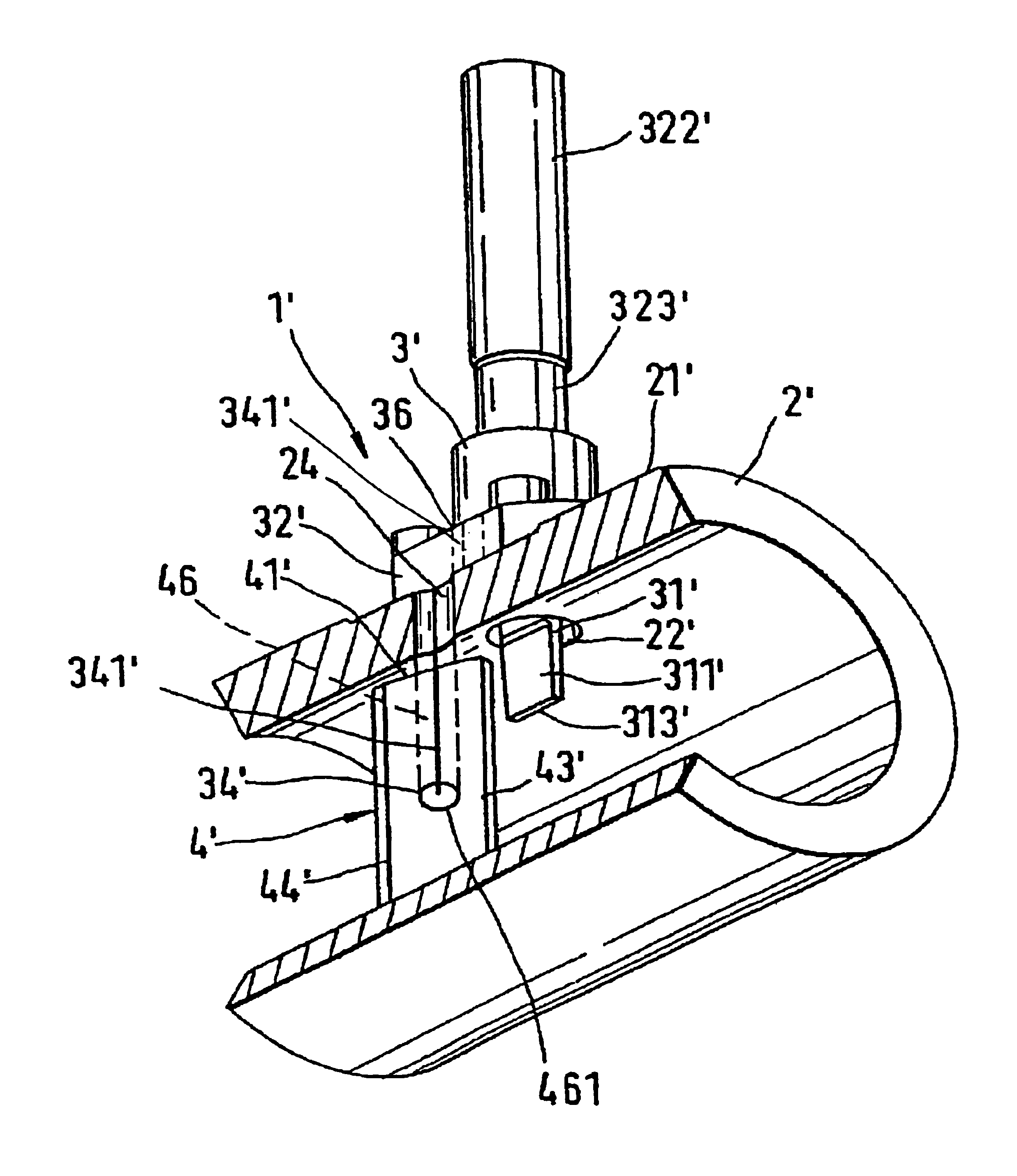
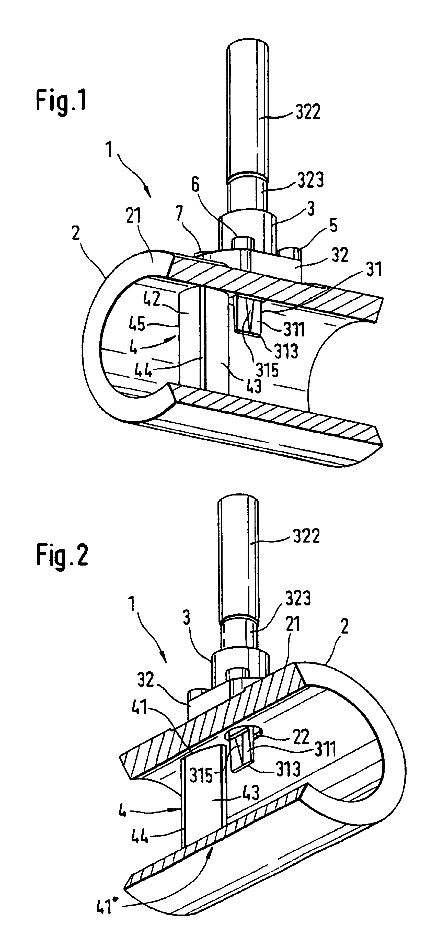
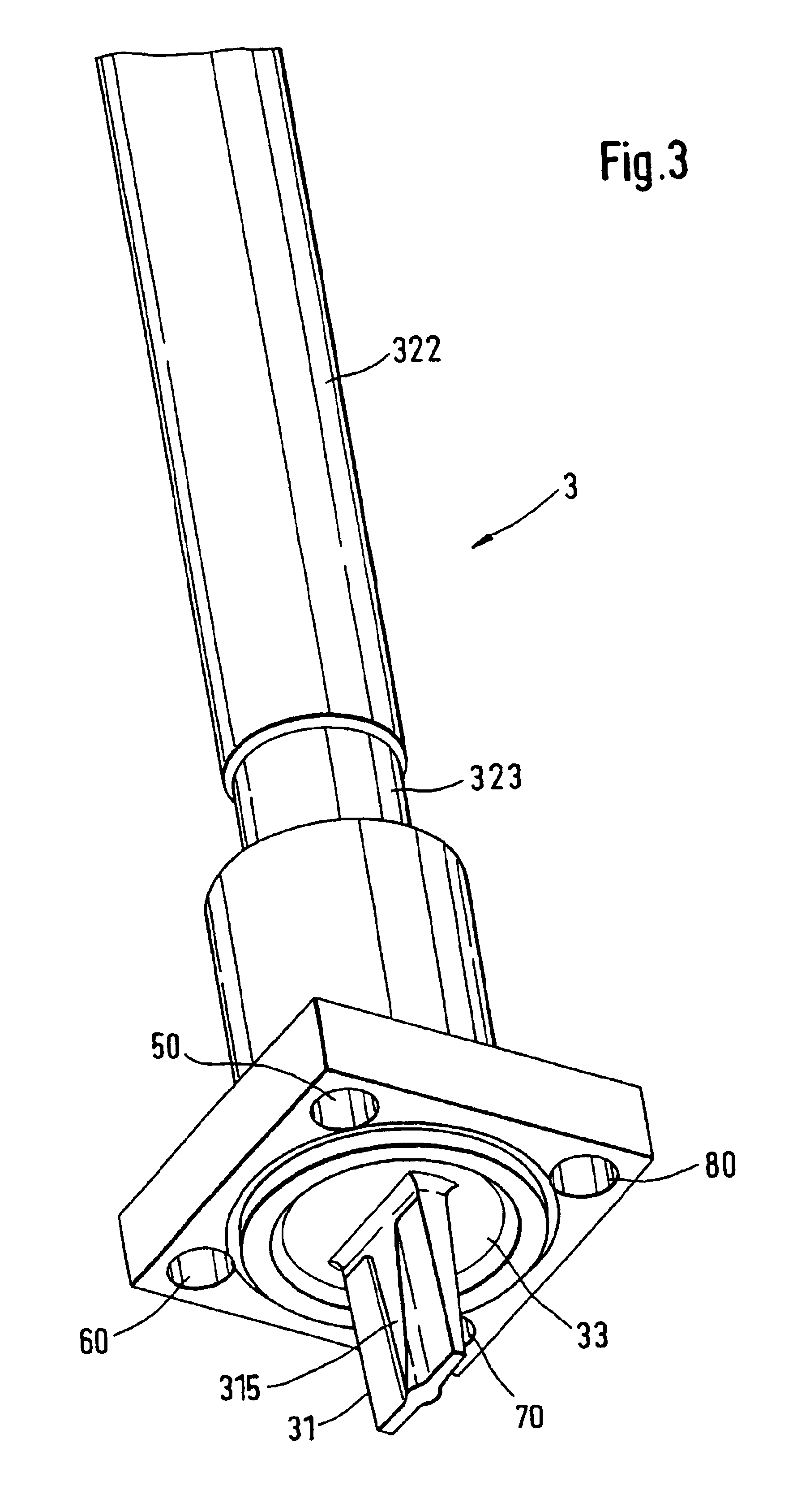
[0068]FIGS. 1 to 4 are described together below, since the details cannot all be represented in each figure. The perspective views shown first in FIGS. 1 and 2, and serving as an overview, of an exemplary embodiment of the first variant show a partly cut open vortex flow pickup 1, seen on the one hand in the direction of flow (FIG. 1) and on the other hand seen counter to the direction of flow (FIG. 2), with a vortex sensor 3 fixed to a tube wail 21 of a measuring tube 2 and protruding through a bore 22. This si preferably a dynamically compensated vortex sensor with a capacitive sensor element, as is described in U.S. Pat. No. 6,003,384, the content of which belongs to the disclosure of this application.

[0069]Arranged along a diameter of the measuring tube 2, in the interior of the latter, is a bluff body 4, which is firmly connected to the measuring tube 2, thereby forming a first fixing location 41, which is represented, and a second fixing location 41*, which is concealed. The c...


PUM


Abstract

A vortex flow pickup serves for measuring mass flow, volume flow or flow velocity of a fluid which is flowing in a measuring tube having a tube wall, and has a temperature sensor arranged in such a way that the vortex flow pickup may also be used together with those fluids which corrode the temperature sensor. A bluff body which produces vortices, and consequently pressure fluctuations, is arranged in the measuring tube. A vortex sensor responding to these pressure fluctuations is fitted downstream of the bluff body in a bore of the tube wall of the measuring tube. The vortex sensor comprises a diaphragm which covers the bore and on which a sensor vane protruding into the fluid is fastened. The temperature sensor is fixed on the bottom of a blind hole of the sensor vane. On the side of the diaphragm lying opposite the sensor vane, a sensor element is fastened. The temperature sensor may alternatively be arranged in a longitudinal bore of the bluff body.

Description

[0001]This application is based on Provisional Application, No. 60 / 330,909, filed Nov. 2, 2001.FIELD OF THE INVENTION[0002]The invention relates to a vortex flow pickup for measuring the volume flow, the mass flow of the flow velocity of the fluid flowing in a direction of flow in a measuring tube, with a bluff body which serves for producing Karman vortices being arranged over a diameter of the measuring tube.BACKGROUND OF THE INVENTION[0003]The volume flow is defined as the volume of fluid flowing through the cross section of the measuring tube per unit of time and the mass flow is defined as the mass of fluid flowing through the cross section of the measuring tube per unit of time.[0004]It is known that, during the operation of a vortex flow pickup of this type, a Karman vortex street is produced downstream of the bluff body and its pressure fluctuations are converted by a vortex sensor into an electrical signal, the frequency of which is proportional to the volume flow or the fl...

Claims


Application Information

Patent Timeline
Patent Type & Authority Patents(United States)
IPC IPC(8): G01F1/32G01F1/86G01F1/76
CPCG01F1/3209G01F1/3218G01F1/3263G01F1/3272G01F1/86G01F1/3273G01F1/3266
Inventor KOUDAL, OLEHOCKER, RAINER
Owner ENDRESS HAUSER FLOWTEC AG
Why Eureka
Try Eureka