Automatic wind-up screen device

Active Publication Date: 2005-09-06
SEIKI JUKO
View PDF17 Cites 33 Cited by
  • Summary
  • Abstract
  • Description
  • Claims
  • Application Information

AI Technical Summary

Benefits of technology

[0023]As described above, according to the automatic winding screen device of the present invention, even if a damper is provided for absorbing impact and collision noise produced during winding, the operationality is improved by making the resistance during screen deployment as small as possible. Also, by controlling the engagement timing of the damper, which may be arbitrarily established, the winding force due to the coil spring may also be effectively operated.
[0024]Also, the one-way clutch mechanism may include a damper-side clutch piece disposed in the shaft fixed to the winding boy; with the damper therebetween, a winding shaft-side clutch piece rotating integrally with the winding shaft and also slidable along the axial direction of the winding shaft, a clutch spring for urging both the clutch pieces in a mating direction, and clutch time-difference operating means for maintaining connection of both clutch pieces during the rotation of the winding shaft by a predetermined number of rotations from a

Problems solved by technology

In such an automatic winding-up screen device, the screen is wound by a rotational urging force due to the swinging of a coil spring, so that the winding speed is increased upon completion of the winding, and the operation frame attached to the extremity of the screen produces a large impact upon colliding with a winding box, making a large collision sound.
For example, in the case of an oil damper, there is frictional resistance between a rubber seal

Method used


Image

  • Automatic wind-up screen device
  • Automatic wind-up screen device
  • Automatic wind-up screen device

Examples


first embodiment

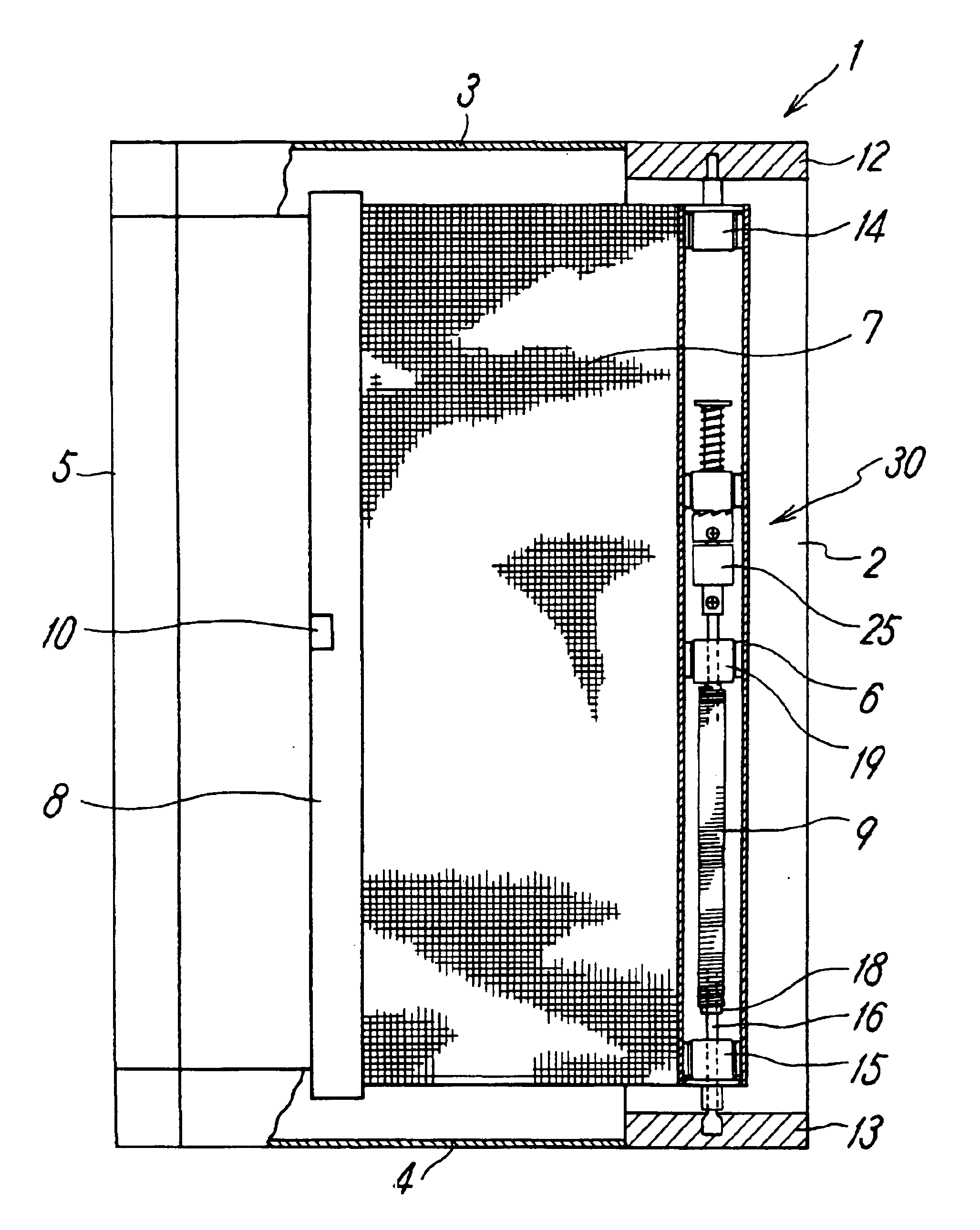
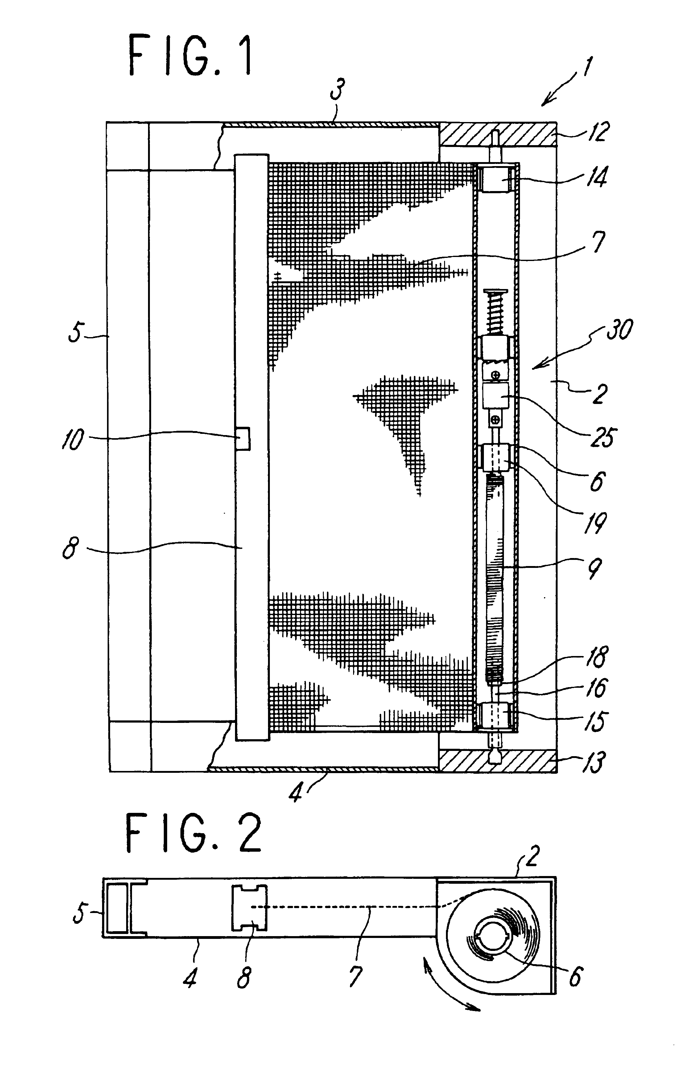
[0043]FIGS. 1 and 2 schematically show the entire structure of an automatic winding screen device according to the present invention, wherein a horizontal pulling screen is exemplified as a screen device; however, the present invention is not limited to the horizontal pulling screen and may also incorporate a case where a vertical pulling screen is automatically wound upward.

[0044]Also, the screen device is shown as being applied for light exclusion, thermal insulation, and insect blocking in an opening of a building; however, it is not limited to these applications and it may also be applied to a dust-blocking screen of a front surface of a shelf and an opening of a meal serving wagon for distributing meals.

[0045]The screen device shown in FIGS. 1 and 2 includes a screen frame 1 provided in an opening of a building, and one side frame 2 of the screen frame 1 is constructed of a winding box supporting a rotatable winding shaft 6 for winding a screen 7 therearound. The screen frame 1...

second embodiment

[0058]In the spirally operating mechanism 44 disposed between the clutch piece 42 and the support shaft 43 shown in the drawings, the screen winding amount from starting to the point when the winding speed is reduced, i.e., when the damper 25 is operated by the mutual connection of the clutch pieces 41 and 42, is established by the length of the male screw 45, while the winding shaft-side clutch piece 42 is driven (screwed) in a direction approaching the damper-side clutch piece 41. FIG. 5 shows the state in that the screen 7 starts to be wound around the winding shaft 6; and FIG. 6 shows the state in that the damper 25 starts to be operated by the mutual connection of the clutch pieces 41 and 42.

[0059]In such a manner, since the screen winding amount from starting to the point when the winding speed is reduced as established by the length of the male screw 45, which prevents the damper 25 from being operated, so that even when an eternal force such as wind is applied to the screen...

third embodiment

[0065]In the screen device both ends of the winding shaft 6 are rotatably supported by the brackets 12 and 13 at upper and lower ends of the winding box via support members 64 and 65, respectively, and a fixed shaft 66 fixed to the upper bracket 12 at an end is inserted into the inside of the winding shaft 6 while a fixed shaft 67 fixed to the lower bracket 13 at an end is inserted thereinto. Then, one end of the coil spring 9 is wound around and fixed to a spring support seat 68 while the other end of the coil spring 9 is rotatably attached to the fixed shaft 66, and the winding shaft 6 is fixedly attached to a spring support seat 69. Therefore, the winding shaft 6 of the screen 7 is connected to the fixed shaft 66 via the coil spring 9.

[0066]As shown in FIGS. 9 to 12 in detail, at the extremity of the fixed shaft 67, an oil damper 75 is provided while a one way clutch mechanism 80 is provided between a rotation shaft 75a of the oil damper 75 and the winding shaft 6.

[0067]In the o...


PUM


Abstract

An automatic winding screen device has a coil spring fixed to a bracket at one end of a winding box, the other end of the coil spring being fixed to a winding shaft, and a damper for alleviating impact and collision noise. Between the damper on a shaft fixed to the winding box and the winding shaft, a one-way clutch mechanism is interposed such that, when the winding shaft is rotated in a screen deploying direction, the connection between the damper and the winding shaft is cancelled while when the winding shaft rotates in a screen winding direction the damper is connected to the winding shaft.

Description

TECHNICAL FIELD[0001]The present invention relates to an automatic winding screen device for dust-blocking, light exclusion, thermal insulation, and insect blocking, and more specifically it relates to an automatic winding screen device using a rotational urging force due to the swinging of a coil spring housed within a winding shaft as a power source for winding the screen and having a damper for absorbing impact and collision noise produced during winding with the coil spring.BACKGROUND ART[0002]A screen device has been widely known in that a screen is wound around a winding shaft having a coil spring as a power source while an open / close operation frame is attached at the extremity of the screen for automatically winding the screen.[0003]In such an automatic winding-up screen device, the screen is wound by a rotational urging force due to the swinging of a coil spring, so that the winding speed is increased upon completion of the winding, and the operation frame attached to the e...

Claims


Application Information

Patent Timeline
IPC IPC(8): E06B9/52E06B9/54
CPCE06B9/54E06B2009/543E06B2009/808
Inventor SUGIYAMA, NOBORUAOKI, TAKASHISAWAGUCHI, NAOTOAOYAMA, TAKESHI
Owner SEIKI JUKO
Why Eureka
Try Eureka