Blade for working machine, and construction and earth-moving machine with the blade

a working machine and blade technology, applied in the field of blades, can solve the problems of reducing the carrying resistance of soil, difficult to increase the quantity of soil carried, and reducing the contact length of excavated soil on the ground, so as to achieve excellent balance on ground contact pressure, reduce power loss such as shoe slippage, and reduce the effect of tractional for

Inactive Publication Date: 2005-09-06
KOMATSU LTD
View PDF10 Cites 53 Cited by
  • Summary
  • Abstract
  • Description
  • Claims
  • Application Information

AI Technical Summary

Benefits of technology

[0015]Because, in the blade of the invention, its first cutting edge is protruded forward of front ends of cutting edges of the end front face sections, the first cutting edge is capable of cutting and breaking up soil and sand positively ahead of the cutting edges disposed on bottom ends of the end front face sections. On the other hand, because the first cutting edge cuts ahead, the substantial digging force of the cutting edges of the end front face sections become smaller than the digging force of the first cutting edge. Thus, as compared to a conventional case, the tractional force applied on the cutting edges of the end front face sections are relaxed so that such resistance forces as digging resistance and soil carrying resistance act upon the first cutting edge and the cutting edges of the end front face sections substantially equally, and the tractional force acts on both the first cutting edge and the cutting edges of the end front face sections effectively. Consequently, soil dug by the cutting edges of the end front face sections and soil dug by the first cutting edge converge smoothly.
[0044]According to the invention, an intersection angle between extensions of the cutting edges of the central front face section and end front face section is set to 25° or less. Preferably, this is set to a range of 15 to 20°. If this intersection angle is 25° or less, an optimum quantity of soil to be loaded on the blade front face of each of the jointed front face section and end front face section can be secured, thereby decreasing the resistance of soil being moved from the end front face section toward the jointed front face section.

Problems solved by technology

Further, by embracing a large quantity of excavated soil within the blade, the weight of the excavated soil swollen in front of the blade and the ground contact length of the excavated soil on the ground are decreased thereby reducing soil carrying resistance.
Thus, the quantity of soil carried is difficult to be increased only by reducing the soil carrying resistance with the art disclosed in the above publication.
Therefore, not only a structure of the entire blade assembly is enlarged but also a number of components is increased, so that a mechanism becomes complicated.
Even if it is intended to load the above-described blade assembly on the medium or small bulldozer just as it is, a sufficient installation space for disposing an extremely complicated mechanism is difficult to secure and therefore, the design on the vehicle needs to be changed largely, thereby leading to a large increase in sales price.
However, they are not intended clearly for reducing consumption horsepower per tractional force on digging / carrying of soil and increasing power consumption efficiency.
As described above, prior arts did not propose any blade which realized effective usage of energy during digging / carrying of soil and low fuel consumption.

Method used


Image

  • Blade for working machine, and construction and earth-moving machine with the blade
  • Blade for working machine, and construction and earth-moving machine with the blade
  • Blade for working machine, and construction and earth-moving machine with the blade

Examples


Embodiment Construction

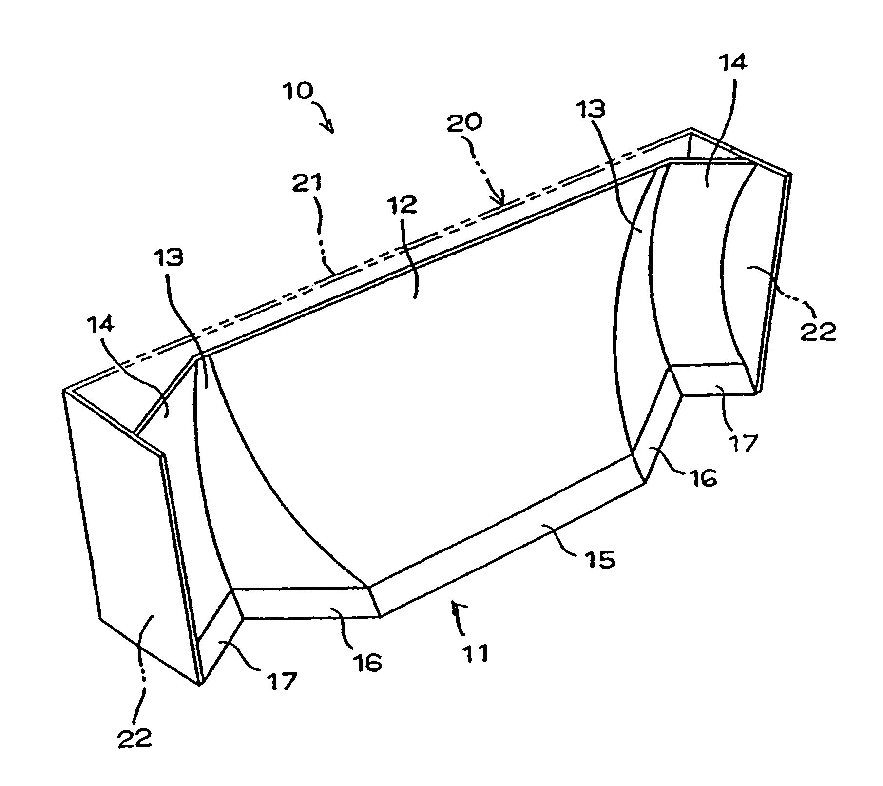
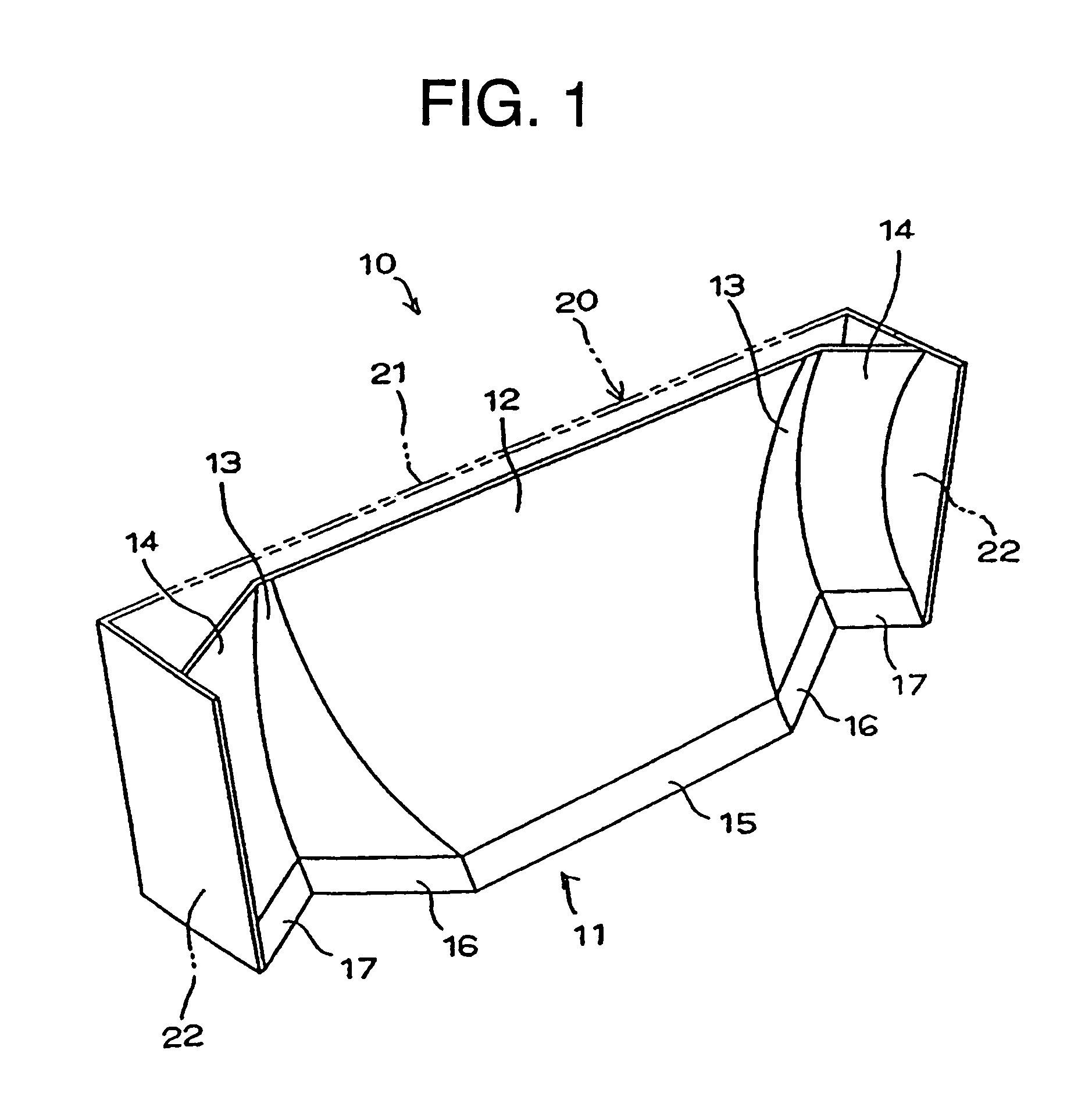
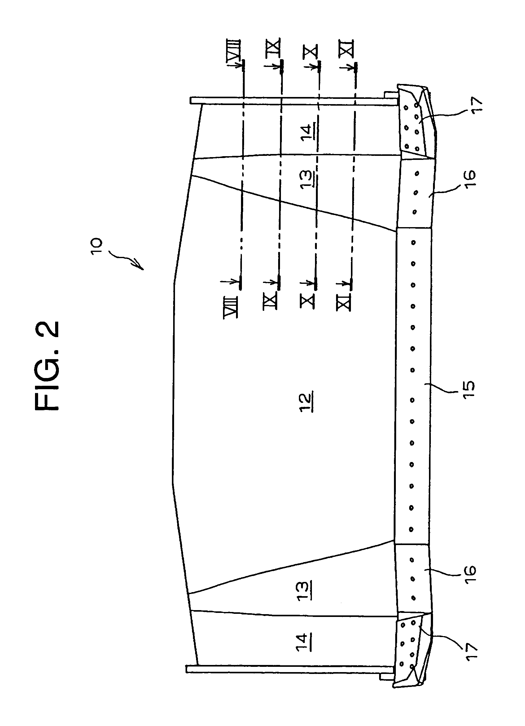
[0067]Hereinafter, a preferred embodiment of the invention will be described in detail with reference to the accompanying drawings. A blade of the invention can be used as a working attachment which is loaded on various kinds of work machines. As the work machines applicable to the invention, for example, construction and earth-moving machines can be mentioned. Although this embodiment will be described by exemplifying a bulldozer (not shown) as, a construction / earth-moving machine, the invention is not restricted to this example, but construction / earth-moving vehicles such as a shovel, backhoe, and motor grader are included.

[0068]The blade 10 according to a typical structure example of the invention is provided with a curved blade front face section 11 which is curved in upward and downward directions as shown in FIGS. 1 to 7. The front face section 11 of the blade is made of a laterally long steel material having a high stiffness and the periphery thereof is integrated with a supp...


PUM


Abstract

A blade preferably adopted to work machines for digging, carrying of soil and leveling, which achieves an increase in a quantity of soil per tractional force with a simple structure to reduce consumption horsepower and increase fuel consumption efficiency thereby leading to low cost, has a central front face section (12) having a linear first cutting edge (15) at a bottom end thereof, a jointed front face section (13) having a second cutting edge (16) which continues from the first cutting edge (15) and extends backward at a predetermined angle, and an end front face section (14) having a third cutting edge (17) which continues from the second cutting edge (16) and extended forward at a predetermined angle.

Description

TECHNICAL FIELD[0001]This invention relates to a blade to be mounted on various kinds of work machines such as a bulldozer and a tractor shovel, and more particularly to a blade of a work machine which is optimally suitable for digging, carrying of soil and leveling, has an excellent working efficiency, and achieves improvement in fuel consumption efficiency and economic performance, and a construction and earth-moving machine provided with the same blade.BACKGROUND ART[0002]Various kinds of work machines such as a bulldozer and a tractor shovel have been often used in working sites for construction, civil engineering and the like. Such kind of the work machine is provided with a blade which is a working attachment. This blade is used widely for bulldozer operation such as digging, carrying of soil, banking, compacting and leveling.[0003]To exert the maximum working efficiency on this work machine, it is important to satisfy various kinds of conditions embraced within the blade is i...

Claims


Application Information

Patent Timeline
Patent Type & Authority Patents(United States)
IPC IPC(8): E02F3/76E02F3/815
CPCE02F3/7618E02F3/815E02F3/8152
Inventor MATSUMOTO, NORIHISATAMARU, MASATAKE
Owner KOMATSU LTD
Why Eureka
Try Eureka