Sorter conveyor

a sorter conveyor and conveyor technology, applied in the direction of conveyors, conveyor parts, packaging, etc., can solve the problem that the rotor is required to be susceptible to the travelling magnetic field, and achieve the effect of less expensiv

Inactive Publication Date: 2005-09-06
CRISPLANT
View PDF16 Cites 41 Cited by
  • Summary
  • Abstract
  • Description
  • Claims
  • Application Information

AI Technical Summary

Benefits of technology

[0036]In order to prevent the cross-belts with articles thereon to start moving when passing curved parts of the stationary tracks due to the apparent centrifugal force, causing the articles to be discharged unintentionally, the conveyor may comprise locking means for preventing the motion of the flexible members of the article-supporting units. Prior art cross-belt units having a complete electric motor on unit may be locked by means of the motor but this opportunity does not exist with the conveyor according to the present invention. The lack of locking means for the cross-belt puts a limit to the maximum conveyance speed of a given conveyor, whereas the existence of locking means allows for higher conveyance speeds and thereby higher efficiency of the conveyor.
[0048]One means for providing horizontal alignment comprises a horizontal wheel on the article-supporting unit, which wheel engages a two-sided track of the track part allowing a very small play between the wheel and the two-sided track, thereby ensuring the correct horizontal position of the rotor with respect to the stationary electric stator part.
[0071]fasten the second tubular member to the first tubular member so as to preserve the tubular shape of the second tubular member as well as the contact between the two tubular members.

Problems solved by technology

The rotor is required to be susceptible to the travelling magnetic field, which may be provided by irregularities of the magnetic properties along the circumference of the rotor, such as the reluctance of the rotor, longitudinal grooves forming teeth and creating an irregularity of the magnetic conducting properties or the presence of permanent magnets in the rotor.

Method used


Image

  • Sorter conveyor
  • Sorter conveyor
  • Sorter conveyor

Examples


Embodiment Construction

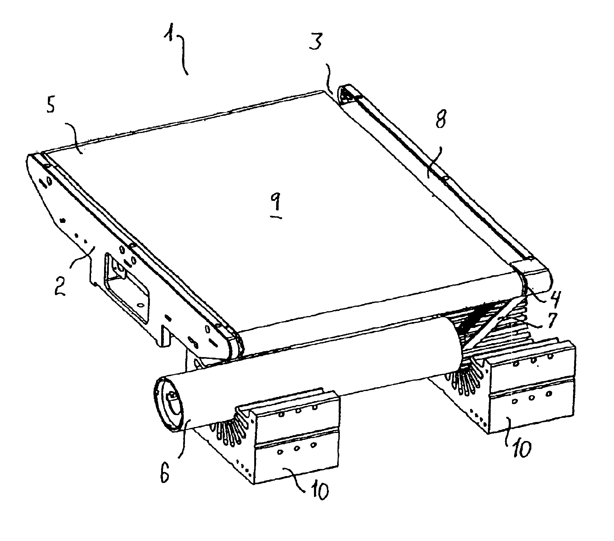
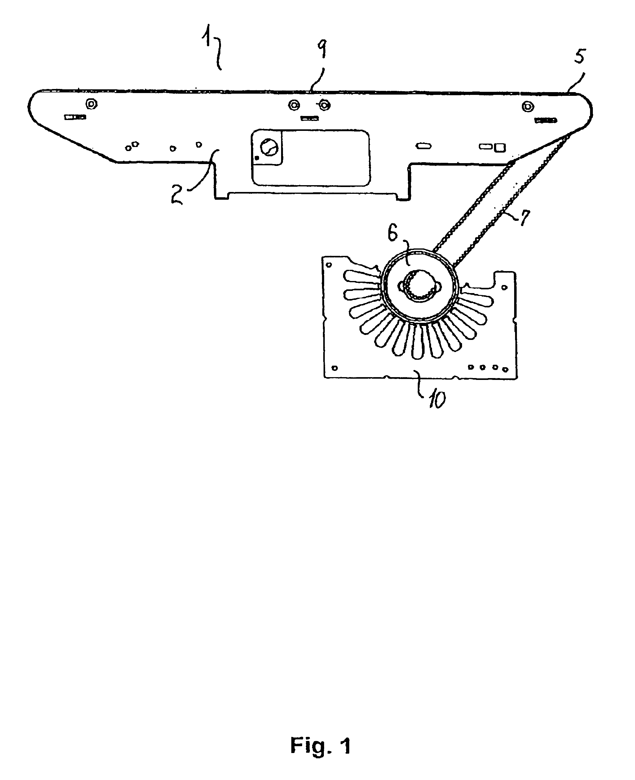
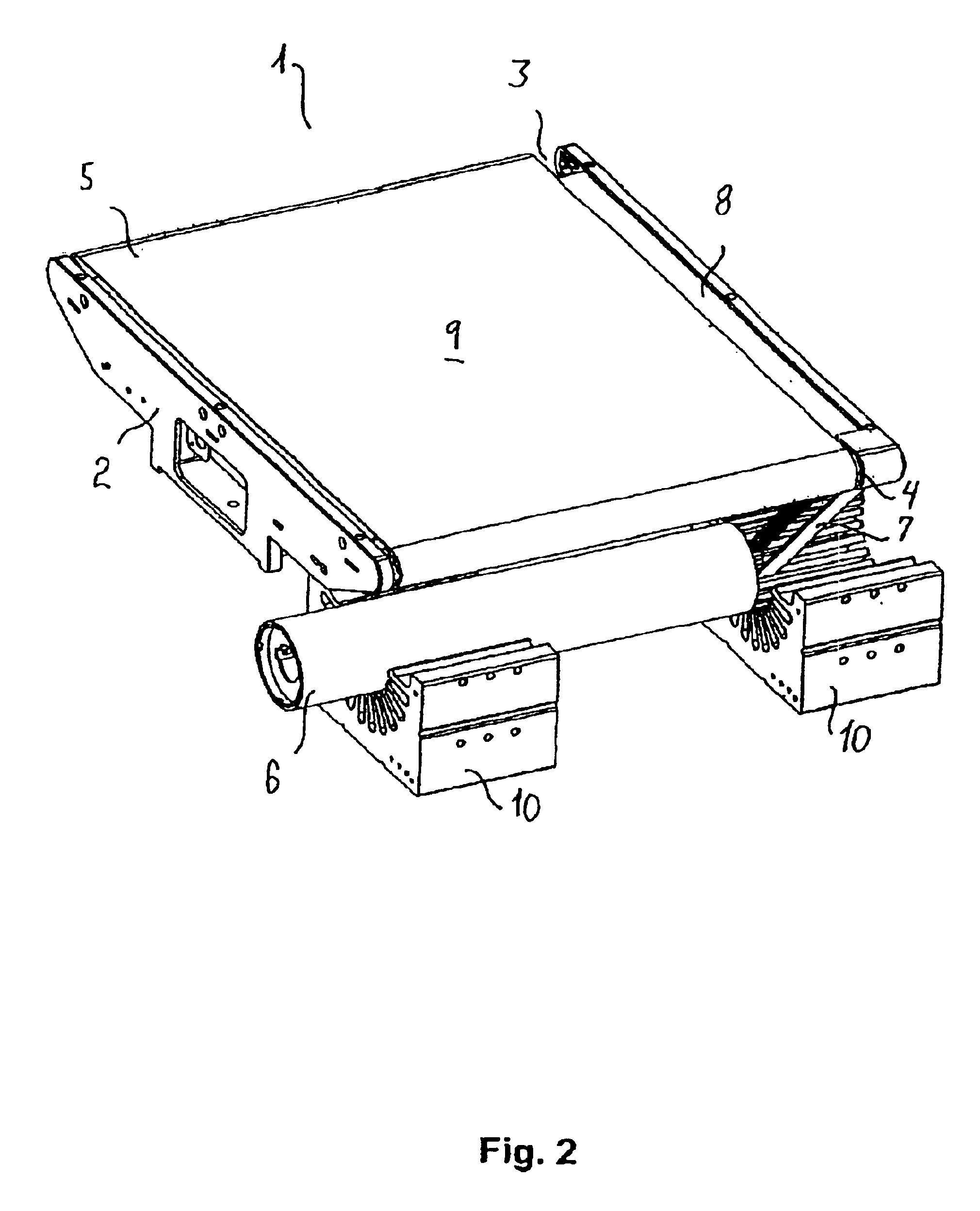
[0096]The cross-belt unit 1 shown in FIGS. 1-3 comprises a frame part 2 supporting two rollers 3, 4 around which the endless cross-belt 5 is running. One of the rollers 4 is the drive roller 4 connected to a rotor 6 by means of a toothed belt 7. The frame part 2 further carries a support plate 8 supporting the cross-belt 5 on the side opposite to the side forming the article-supporting surface 9 of the cross-belt unit 1. The rotor 6 is situated above two stationary electric stator parts 10.

[0097]The schematic view in FIG. 4 of the first embodiment of the cross-belt unit 1 may be compared to a second embodiment of a cross-belt unit 1′ shown in FIGS. 5-8. In the second embodiment, the transmission means comprises an intermediate roller 11 connected at a first end to the rotor 6 by means of a first belt and at a second end thereof to the drive roller 4 by means of a second belt 7′. This configuration provides a higher freedom of design and of changing and makes variations of a given de...


PUM


Abstract

A sorter conveyor having cross-belts for supporting and discharging article is disclosed, wherein the cross-belts are driven by interaction between a rotor moving with the cross-belts and stationary electric stator parts, wherein the rotor is arranged separate from the cross-belt and is connected to a drive roller with a transmission. Further is disclosed such sorter conveyors having tilt-trays driven by interaction between rotors moving with the tilt-trays and stationary electric stator parts, as well as such sorter conveyors which are driven along the stationary track by means of stationary linear motor stator parts interacting with the reaction means. Lastly, rotors and the manufacture of such rotors are disclosed.

Description

[0001]This application is the national phase under 35 U.S.C. § 371 of PCT International Application No. PCT / DK02 / 00045 which has an International filing date of Jan. 22, 2002, which designated the United States of America and which claims priority on Danish Patent Application number DK PA 2001 00107 filed Jan. 22, 2001, the entire contents of which are hereby incorporated herein by reference.TECHNICAL FIELD[0002]The present invention relates to sorter conveyors having cross-belts for supporting and discharging articles, wherein the cross-belts are driven by interaction between reaction means moving with the cross-belts and stationary electric stator parts, also known as Arch Induction Motors.[0003]The invention further relates to sorter conveyors having tilt-trays for supporting and discharging articles, wherein the tilting of the trays are driven by interaction between reaction means moving with the tilt-trays and stationary electric stator parts.[0004]Furthermore, the invention re...

Claims


Application Information

Patent Timeline
Patent Type & Authority Patents(United States)
IPC IPC(8): B65G17/32B65G23/00B65G17/34B65G47/74B65G47/96B65G23/23B65G47/10
CPCB65G17/345B65G23/23B65G47/96B65G47/962B65G2201/02B65G2207/18
Inventor MILLER, HENRIKPEDERSEN, JOHN NYMANNSORENSEN, DENNISJOCHUMSEN, HANS HENRIKMADSEN, THOMAS SCHMIDT
Owner CRISPLANT
Why Eureka
Try Eureka