Vertical lift assembly

a vertical lift and assembly technology, applied in the direction of conveyor parts, packaging, transportation and packaging, etc., can solve the problems of increased failure probability, belt stress, and jamming of the faster conveyor

Active Publication Date: 2005-09-06
TKF CONVEYOR SYST LLC
View PDF46 Cites 31 Cited by
  • Summary
  • Abstract
  • Description
  • Claims
  • Application Information

AI Technical Summary

Benefits of technology

[0007]The present invention relates to an improved vertical lift assembly for use with a conveyor, comprising: a stationary member; a raisable member mounted on the stationary member for vertical movement between a first recessed position and a second intercepting position; an intercepting means mounted on the raisable member; a lift means for selectively raising the raisable frame between the first and second positions; and at least three of a hinge for joining in planar relationship the raisable member to the stationary member, each hinge comprising a first stationary joint affixed to the stationary member, a second joint affixed to the raisable member, and an third joint intermediate between and in communication with both the first and second joints; wherein in the first position, an upper engagement surface of the intercepting means is in a recess position below a transfer surface of the conveyor and out of potential engagement an object on the conveyor transfer surface; and wherein in the second position, the upper engagement surface is in a raised position, above the transfer surface of the conveyor for selected engagement with the object on the transfer surface.
[0008]The invention also relates to an improved diverting conveyor unit for diverting objects from a conveyor. The diverting conveyor unit comprises a conveyor assembly comprising a support structure; a plurality of spaced rollers having an upper transfer surface, mounted in the support structure; a drive apparatus for driving the rollers; and a main direction control device for operating the drive apparatus. The diverting conveyor unit also comprises: a vertical lift diverter assembly comprising: a stationary member; a raisable member mounted on the stationary member for vertical movement between a first recessed position and a second diverting position; a powered diverter means mounted on the raisable member; a lift means for selectively raising the raisable frame between the first and second positions; and at least three of a hinge for joining in planar relationship the raisable member to the stationary member. Each hinge comprises a first stationary joint affixed to the stationary member, a second joint affixed to the raisable member, and an third joint intermediate between and in communication with both the first and second joints. In the first position, an upper engagement surface of the powered diverter means is recessed below the transfer surface of the conveyor and out of potential diverting engagement with an object on the conveyor transfer surface. In the second position, the upper engagement surface is raised above the transfer surface of the conveyor for selected diverting engagement with the object on the transfer surface.
[0009]The invention also relates to an improved vertical lift assembly for use with raising an object, comprising a stationary member; a raisable member mounted on the stationary member for vertical movement between a first position and a second position; a lift means for selectively raising the raisable frame between the first and second positions; and at least three of a hinge for joining in planar relationship the raisable member to the stationary member, each hinge comprising a first stationary joint affixed to the stationary member, a second joint affixed to the raisable member, and an third joint intermediate between and in communication with both the first joint and the second joint.

Problems solved by technology

In such applications the lateral transfer to slower conveyors can cause jams on the faster conveyor due to the longer time required to effect the lateral transfer relative to the transit time of the goods on the faster main conveyor.
This can cause stress to the belts, with an increased chance for failure.
Further, it can create difficulties in controlling the rate of speed of the diverting rollers.
This may be inefficient and may cause tilting of objects being diverted, which may be undesirable in certain instances.
Generally, conventional devices have not satisfactorily solved the problem of having vertical lift with no substantial tilting and without stretching of the transfer belts or drive belts for diverter rollers.
In addition, conventional diverters may have a multitude of moving parts and may need to be manufactured to fine tolerances for operation, both of which will tend to increase the cost of such systems.

Method used


Image

  • Vertical lift assembly
  • Vertical lift assembly
  • Vertical lift assembly

Examples


Embodiment Construction

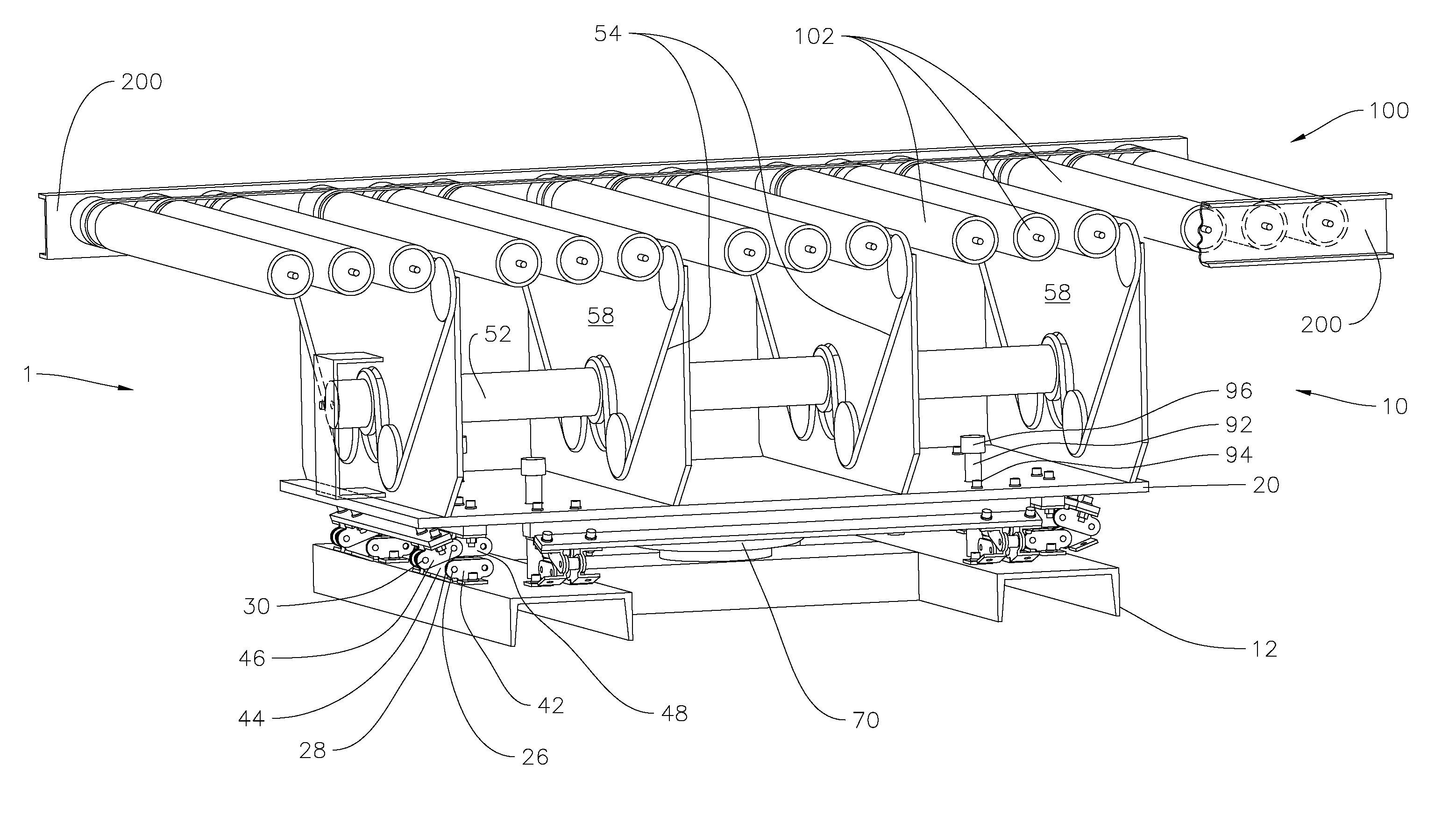
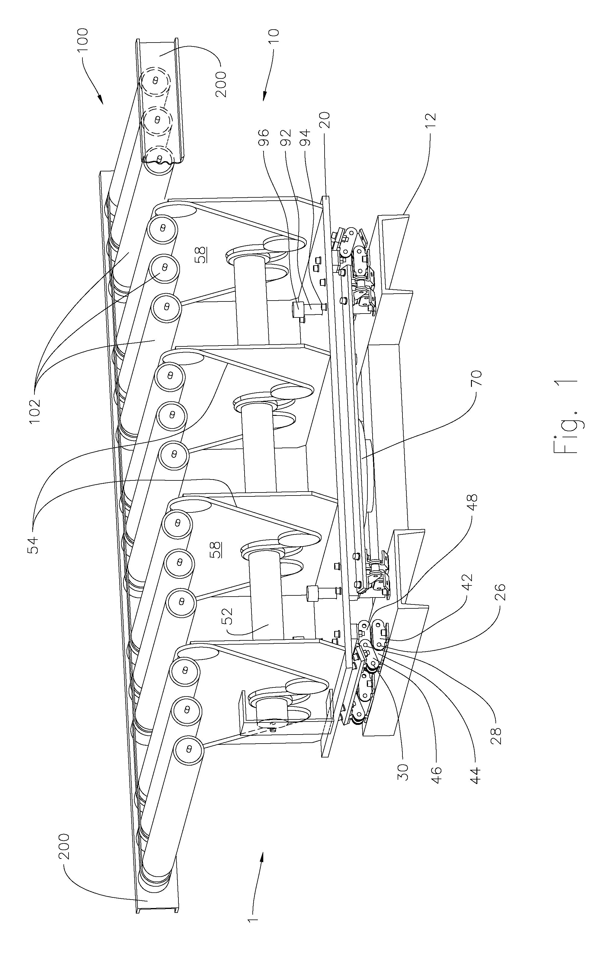
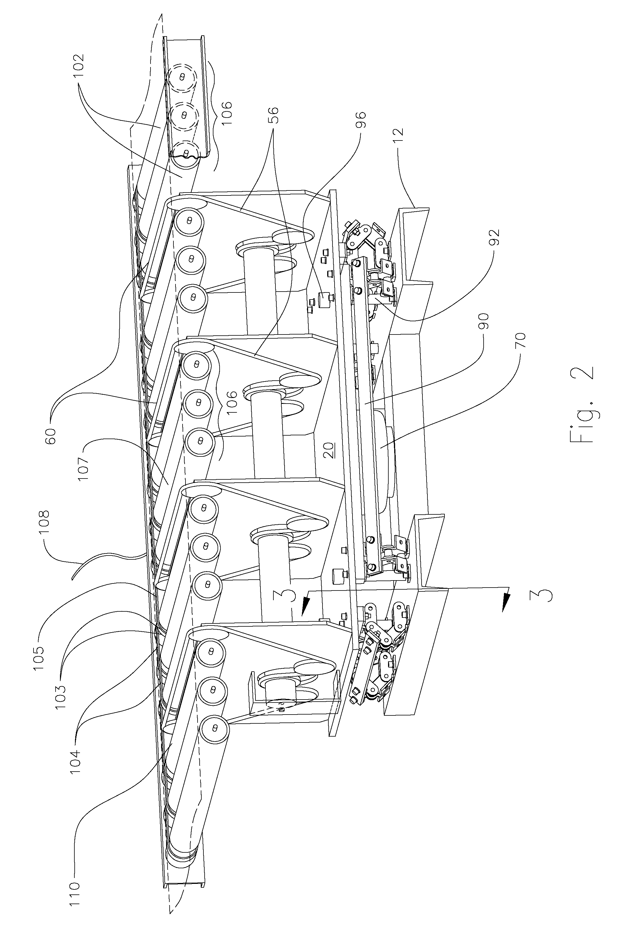
[0015]FIGS. 1 and 2 show a portion of a roller conveyor system comprising an intercepting conveyor unit 1. The intercepting conveyor unit can be positioned along the roller conveying pathway. The unit serves to intercept an object passing along the conveyor, by either stopping the object, or by diverting the object off of the roller conveyor to a side of the roller conveyor. The intercepting conveyor unit can therefore be a stopping conveyor unit that comprises an object stop, or a diverting conveyor unit that comprises a diverting means, depending on the utility required. Examples of conventional diverting conveyors are those described in U.S. Pat. Nos. 4,174,774 and 4,798,275, hereby incorporated by reference.

[0016]The intercepting conveyor unit shown in the Figures is a diverting conveyor unit 1. The diverting conveyor unit 1 comprises a portion of a conveyor assembly 100 and a vertical lift diverter assembly 10. The conveyor assembly 100 comprises a support structure comprising ...


PUM


Abstract

A vertical lift assembly for raising a plurality of diverting belts between rollers of a roller conveyor, to engage and raise an object from the surface of the conveyor, and to divert it to the side of the conveyor. The vertical lift assembly uses a plurality of hinges to join together a stationary frame, as a base, and a raisable plate on which sets the diverting belt assembly. The hinge is formed from a section of roller chain. A pair of hinges is disposed along each side of the stationary frame and raisable plate. The hinges provide tilt-free lift of the diverting belt assembly.

Description

BACKGROUND OF INVENTION[0001]This invention relates to a vertical lift assembly for use in raising an object, and particularly for use as a diverting assembly for a roller conveyor system.[0002]With increasing automation of manufacturing and warehousing operations, conveyors are becoming ever more relied upon for high-speed, reliable transfer of goods. Often, continuous manufacturing processes turn out goods faster than subsequent processing and finishing stations can perform. In order to accommodate this mismatch, diverting conveyors are used, for example, to distribute the product from the output conveyor of a fast stage to a number of input conveyors of subsequent slower stages. In such applications the lateral transfer to slower conveyors can cause jams on the faster conveyor due to the longer time required to effect the lateral transfer relative to the transit time of the goods on the faster main conveyor. In addition, the need for faster, more facile diverting conveyors requir...

Claims


Application Information

Patent Timeline
Patent Type & Authority Patents(United States)
IPC IPC(8): B65G47/34B65G47/53B65G47/54
CPCB65G47/34B65G47/54B65G2201/02B65G2207/18
Inventor EUBANKS, RONALD L.RADFORD, DAVID NORMAN
Owner TKF CONVEYOR SYST LLC
Why Eureka
Try Eureka