
Fiber holder

a fiber and holder technology, applied in the field of fiber holders, can solve the problems of not being able to reliably and conveniently secure the fiber holder to the user, prior art devices had great difficulty in removing the holder to the device, and the fiber was not presented in the easiest and most convenient manner to the user, and achieves the effect of easy maintenan

Inactive Publication Date: 2005-09-06
LEE THOMAS M
View PDF14 Cites 30 Cited by
  • Summary
  • Abstract
  • Description
  • Claims
  • Application Information

AI Technical Summary

Benefits of technology

[0010]It is an object of the instant invention to provide a fiber holder which easily maintains the fiber in predetermined locations and divided from other fiber in the group.
[0011]Another object is to provide a fiber holder which can be easily manipulated to provide access to the desired fiber of a given color, nature, and of a preselected length.
[0012]Still another object is to enable the user to pull out individual threads of fiber without entangling or jamming either the hank or interfering with the other hanks of fiber.
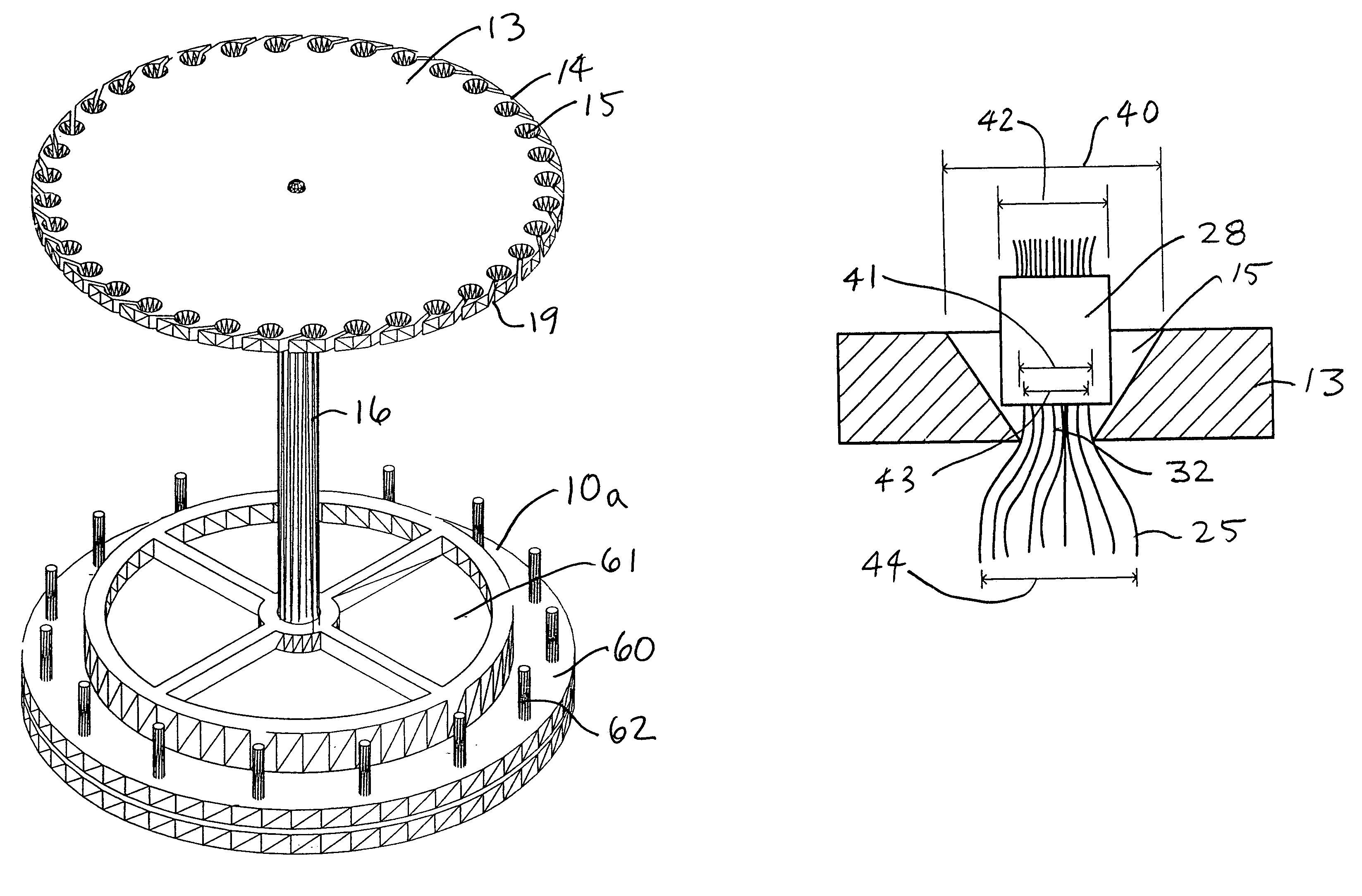
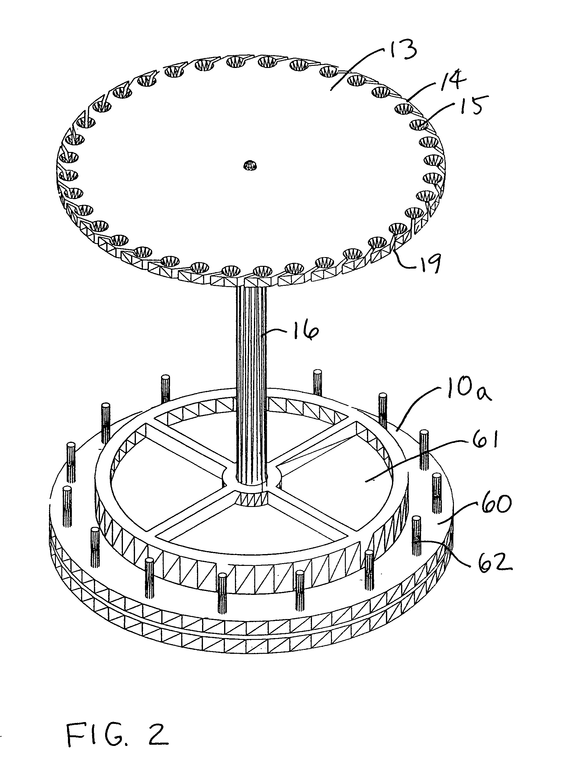
[0014]The invention comprises a suspension plate such as a circular, transparent, plastic disc having a plurality of truncated conic circular bores located equidistant from the center of the disc and being substantially equidistant from each other. The plate could be wood or other material. Each bore has a larger diameter opening on the top of the disc and a smaller diameter opening on the bottom of the disc. A plurality of generally radial slots equal in number to the number of bores are located on the disc to communicate between each bore and the outer edge of the disc. Each bore provides a device wherein a hank of fiber, cut into substantially equal lengths to other hanks and divided by color and / or nature can be presented for display and use. The hank of fiber of like color and / or nature is bound by a knob-like binder that can be captured in one of the bores, with the hank of fiber suspended down from the disc, thus locking the hank of fiber in place relative to other hanks and to the disc. The binder is captured because its effective diameter is between the diameters of the upper and lower openings of the bore. The slot allows the hank of fiber to be axially placed within the bore without the hank having to be threaded longitudinally into the bore. The disc can be rotatably mounted, by means of a support, to a base. The base can sit on a surface or can be attached to a surface. Because the disc is rotatably mounted, it has carousel or “Lazy-Susan” functionality, to facilitate user access to the hanks of fiber.

Problems solved by technology

Because of the physical nature of the hanks of fiber, prior art devices had great difficulty securing the hanks reliably but also removably to the devices.
Furthermore, the prior art devices did not present the fiber to the user in the easiest and most convenient manner.
One of the most challenging and creative activities relating to the sport and hobby of fishing is the creation of decorated fish hooks generally called flies.
Part of the challenge of fly tying is the vast array of raw materials which are used for that activity.
When the various colors and types of floss are stored in a random manner as such as in a box or other container, they tend to become mixed together become hard to find and become quite difficult to gather into the effective parallel bundles which are usually necessary to carry out the fly tying operation.
However in most cases, the storage systems which hold the floss in an orderly fashion are difficult to reach and difficult to identify and access the desired floss.

Method used


Image

  • Fiber holder
  • Fiber holder
  • Fiber holder

Examples


Embodiment Construction

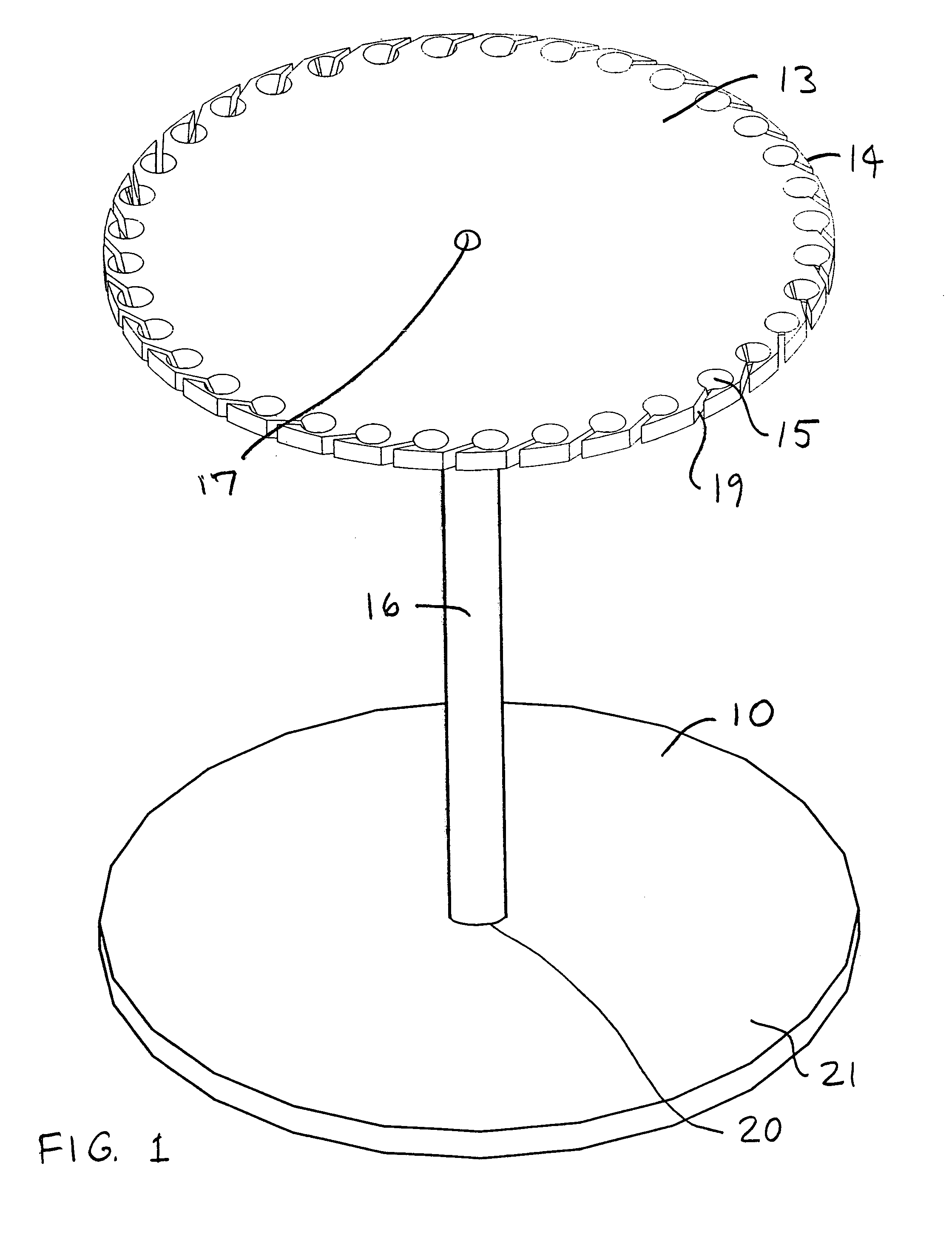
[0036]A fiber holder is seen as element 10 in FIG. 1 and includes a plate which may be a generally planar, transparent, plastic disc 13 and which has a plurality of circular bores or holes 15 located substantially equidistant from the center of the disc 13. The disk could also be made of wood or other material. On substantially the same radius as the holes 15 are a corresponding number of generally radially extending grooves or slots 19 each of which communicates between a bore 15 and the outer edge 14 of the disc 13. The grooves may be radial or may be at an angle to the radius.

[0037]Attached to the disc 13 is a plastic or other type support 16 which are secured by means of a fastening system 17. The support 16 is secured by means of a fastening system 20 to a base 21 which contacts a support surface such as a table surface or a wall. The disc 13 rotates in a “lazy-Susan” manner with respect to the surface, and typically rotates in a “lazy-Susan” manner with respect to the base 21....


PUM


Abstract

The invention is a suspension plate system for providing access to hanks of fiber. The system may include a circular, transparent, plastic disc having a plurality of truncated conic circular bores located equidistant from the center of the disc and being substantially equidistant from each other. Each bore has a larger diameter opening on the top of the disc and a smaller diameter opening on the bottom of the disc. A plurality of generally radial slots equal in number to the number of bores are located on the disc to communicate between each bore and the outer edge of the disc. Each bore provides a device wherein a hank of fiber, cut into substantially equal lengths to other hanks and divided by color and / or nature can be presented for display and use. The hank of fiber of like color and / or nature is bound by a knob-like binder that can be captured in one of the bores, with the hank of fiber suspended down from the disc, thus locking the hank of fiber in place relative to other hanks and to the disc. The binder is captured because its effective diameter is between the diameters of the upper and lower openings of the bore. The slot allows the hank of fiber to be axially placed within the bore without the hank having to be threaded longitudinally into the bore.

Description

CROSS-REFERENCE TO RELATED APPLICATIONS[0001]Not Applicable.STATEMENT REGARDING FEDERALLY SPONSORED RESEARCH OR DEVELOPMENT[0002]This invention has been created without the sponsorship or funding of any federally sponsored research or development program.BACKGROUND OF THE INVENTION[0003]1. Field of the Invention[0004]The invention relates to a fiber holder, and particularly a fiber holder for securing and presenting hanks of fiber which have been separated by color and / or nature.[0005]2. Prior Art[0006]Various devices have been provided in the past for holding hanks of fiber wherein the fiber may be separated by colors and / or nature and displayed for selection and use. Because of the physical nature of the hanks of fiber, prior art devices had great difficulty securing the hanks reliably but also removably to the devices. Furthermore, the prior art devices did not present the fiber to the user in the easiest and most convenient manner.[0007]This invention particularly concerns the f...

Claims


Application Information

Patent Timeline
IPC IPC(8): A47F5/02B07C7/00B07C7/04A47F7/00
CPCA47F5/02A47F7/0021
Inventor LEE, THOMAS M.
Owner LEE THOMAS M
Learn More