Crop discharge spout arrangement of an agricultural harvesting machine

a technology of agricultural harvesting machine and discharge spout, which is applied in the direction of digger harvester, agriculture, agricultural tools and machines, etc., can solve the problems of interference, loss of time in the operation chain,

Active Publication Date: 2005-09-06
DEERE & CO
View PDF11 Cites 27 Cited by
  • Summary
  • Abstract
  • Description
  • Claims
  • Application Information

AI Technical Summary

Benefits of technology

[0009]In this way, the length of the discharge spout arrangement becomes variable. When the transport vehicles operate alongside each other, they operate as trailers or as other silo vehicles, and the outlet end of the discharge spout arrangement can always be positioned optimally over the filling surface. Thereby the load capacity of the vehicles is utilized optimally. Waiting times can be avoided, and the chain of events in the operation of the chopper, proceeds more cost-effectively. The operator of the harvesting machine and the operator of the transport vehicle are relieved of some of their duties, since a predetermined fixed spacing between the silo vehicle and the front harvesting attachment need not be maintained with absolute precision. Since the spacing between the harvesting machine and the transport vehicle can be varied and can be selected sufficiently large, the danger of a collision between the transport vehicle, and in particular, a relatively wide front harvesting attachment, is reduced. In the chain of vehicles in the operation of a chopper, the most varied transport vehicles are frequently used and each tractor operator has his own preferred spacing safety margin from the forage harvester. The adjustable second spout element can accommodate these different spacings. During operation on a slope and in wet weather, the transport vehicles frequently slide easily down the slope. This change in spacing to the harvesting machine can also be accommodated by the adjustable discharge spout arrangement. During the operation of a chopper with transport trailers towed by a harvesting machine, wind losses can be avoided in that the outlet end of the discharge spout arrangement is conducted more closely to the transport vehicle. Here too, a better accommodation to transport vehicles of varied configurations is possible.
[0014]Particularly, when the second element of the discharge spout arrangement is in its extended position, large forces must be absorbed that result from the operating movement of the harvesting machine and the harvested crop deflected by the second element. These forces are absorbed preferably by arms and rolls that transmit the forces from the second spout element to the first spout element. Such arms may be arranged on opposite sides of the second spout element so as to extend along opposite sides of, and engage opposite side surfaces of, the first spout element. The axes of rotation of the rolls are appropriately oriented transverse to the axis of sliding of the second spout element, so that the rolls can roll along the surface or surfaces of the first spout element.

Problems solved by technology

Frequently, the distance between the forage harvester and the transport vehicle is too large, so that the transport vehicle is filled only on one side.
This can lead to a loss of time in the chain of events in the operation of the chopper if the transport vehicle must be changed too early, since it cannot be loaded any further.
In addition, in case of strong side winds during the deposit of the harvested crop onto the transport vehicle, losses can result if the flap of the discharge spout arrangement is at too great a distance from the trailer.
They do, however, have the disadvantage that they can have the effect of an interference in many other operating conditions in which the transport vehicle is already operating close to the forage harvester.

Method used


Image

  • Crop discharge spout arrangement of an agricultural harvesting machine
  • Crop discharge spout arrangement of an agricultural harvesting machine
  • Crop discharge spout arrangement of an agricultural harvesting machine

Examples


Embodiment Construction

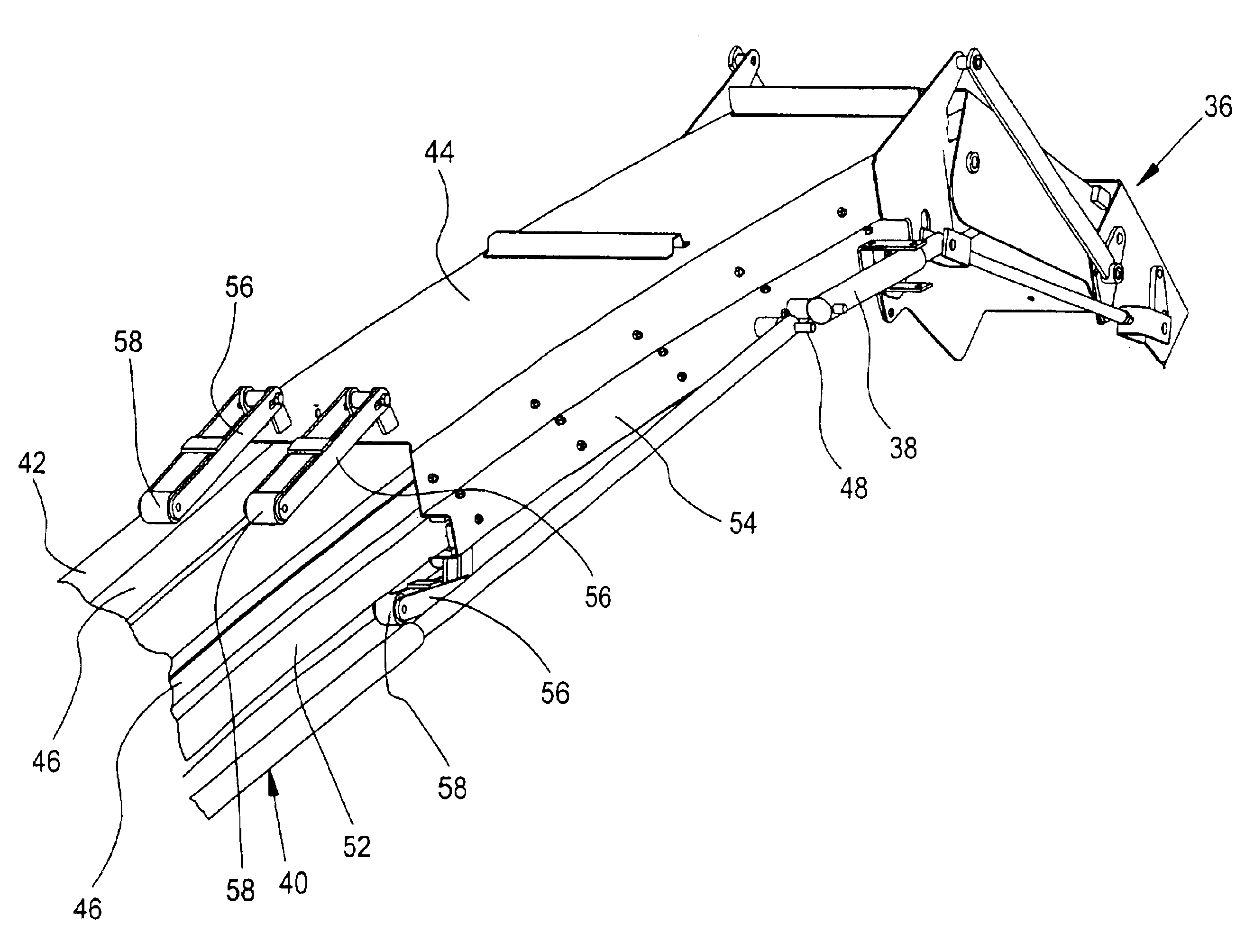
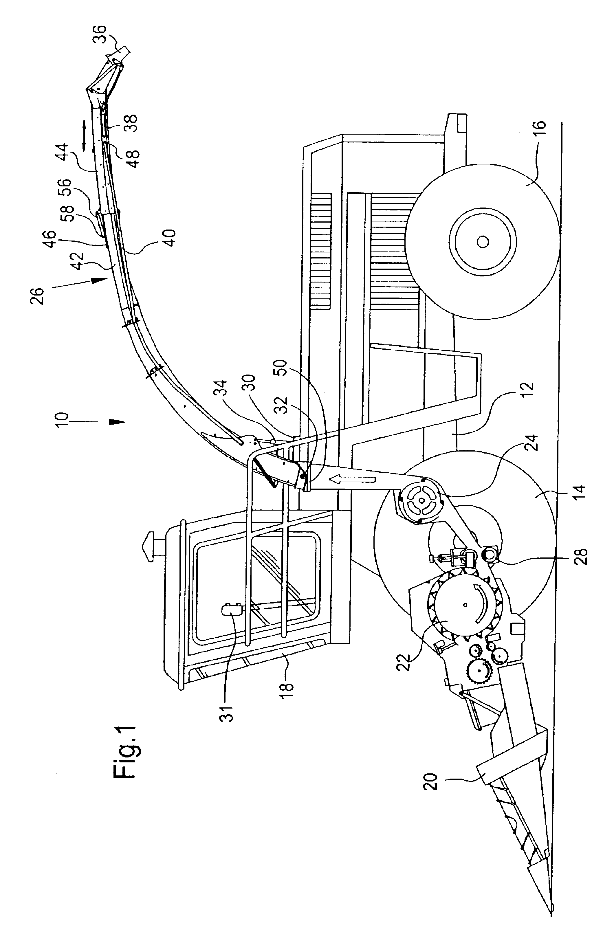
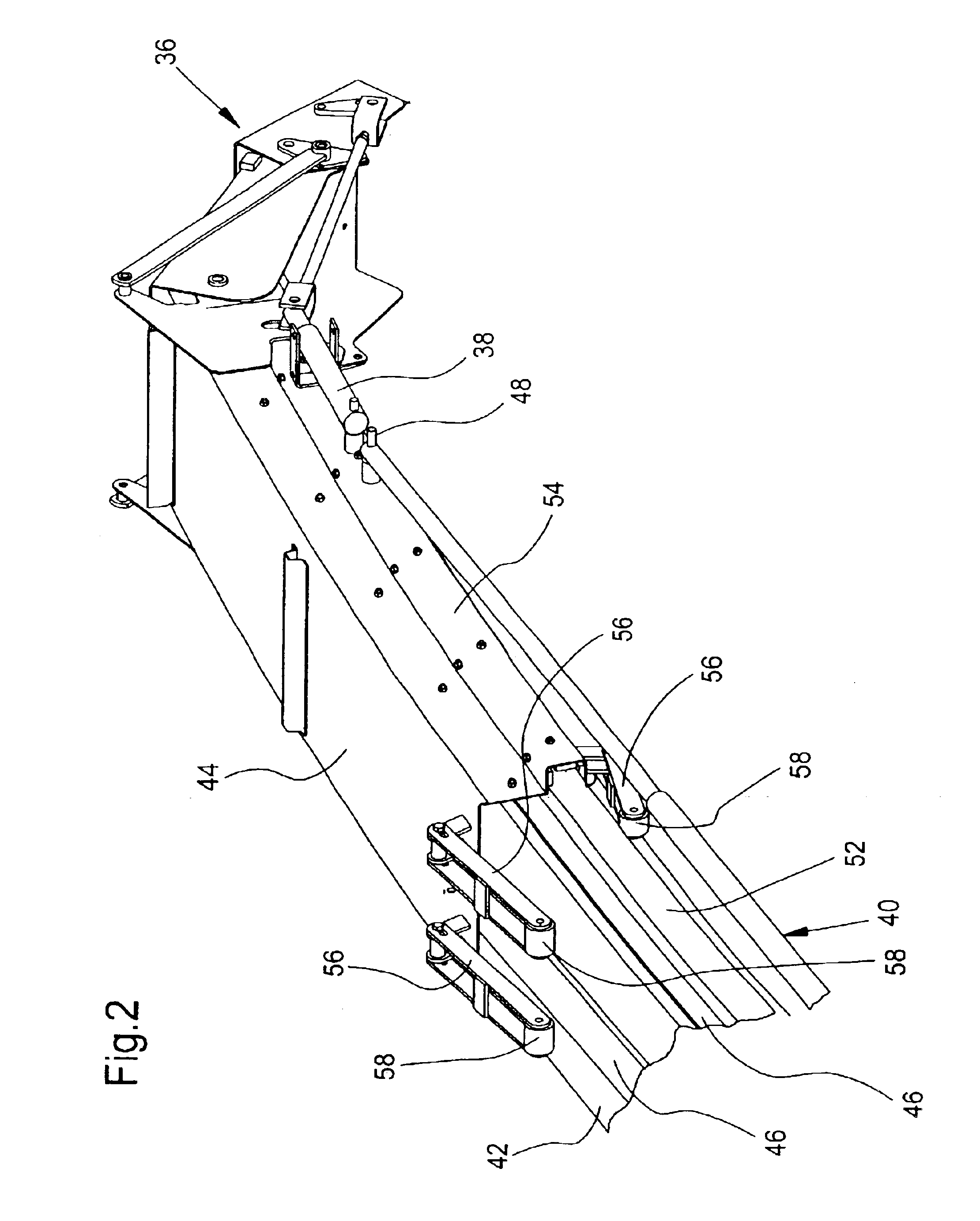
[0018]A harvesting machine 10 in the form of a self-propelled forage harvester is built on a frame 12 that is carried by front and rear pairs of transversely spaced wheels 14 and 16, respectively. The harvesting machine 10 is controlled from an operator's cab 18 from which a harvested crop take-up arrangement 20 can be viewed. Crop, such as corn, grass or the like, taken up from the ground by means of the harvested crop take-up arrangement 20, is conducted to a chopper drum 22 which chops it into small pieces and delivers it to a conveyor or blower arrangement 24. The crop leaves the harvesting machine 10 to a transport vehicle operating alongside through a discharge spout or duct arrangement 26 mounted to the harvesting machine for swinging about a vertical axis. Between the chopper drum 22 and the conveyor arrangement 24, there extends a post-chopper reduction or kernel processor arrangement 28 through which the crop to be conveyed is conducted tangentially to the conveyor arrange...


PUM


Abstract

A discharge spout arrangement of an agricultural harvesting machine through which harvested crop processed by the harvesting machine can be transported to a transport vehicle. The discharge spout arrangement includes a first spout element connected with the harvesting machine. A second spout element is mounted to and defines an extension the first spout element. The second spout element is slidably movable between fully retracted and extended positions respectively wherein a discharge end of the second spout element is spaced a minimum and a maximum distance from a discharge end of said first spout element.

Description

FIELD OF THE INVENTION[0001]The invention concerns a discharge spout arrangement of an agricultural harvesting machine, through which harvested crop processed by the harvesting machine can be conducted to a transport vehicle.BACKGROUND OF THE INVENTION[0002]Forage harvesters are harvesting machines that take up harvested crop from the ground, chop it, and deposit it through a discharge spout arrangement upon a deposit surface of a transport vehicle operating alongside or towed by the forage harvester. In order to fill the transport vehicle in a controlled manner, the direction of ejection can be varied by a discharge spout arrangement rotating about a vertical axis. In some embodiments, the height of the outlet end of the discharge spout arrangement can also be varied in that the discharge spout arrangement can be pivoted about a horizontal axis. Furthermore, an adjustable flap is provided at the outlet end of the discharge spout arrangement in order to provide an input for the dire...

Claims


Application Information

Patent Timeline
Patent Type & Authority Patents(United States)
IPC IPC(8): A01D43/08A01D43/00
CPCA01D43/087
Inventor GROSSJOHANN, HARALDBISSEN, LAURENT
Owner DEERE & CO
Why Eureka
Try Eureka