Sample measurement device and sample measurement method

a measurement device and sample technology, applied in measurement devices, color/spectral property measurements, instruments, etc., can solve the problems of delayed measurement, inability to synchronize two measurements, complex control, etc., and achieve the effect of reducing the waiting time of the first processing unit and reducing the holding hole of the relay section

Pending Publication Date: 2020-10-01
SYSMEX CORP
View PDF5 Cites 0 Cited by
  • Summary
  • Abstract
  • Description
  • Claims
  • Application Information

AI Technical Summary

Benefits of technology

[0023]For example, when the second containers are held in the respective holding holes of the relay section, the first processing unit cannot transfer the second container to the relay section until there is a vacant holding hole in the relay section. In this regard, according to the sample measurement device of the present aspect, the second container can be stored in the holding section. Therefore, the second processing unit can transfer the second container positioned in the relay section to the holding section at an arbitrary timing, and can prepare a vacant holding hole in the relay section as quickly as possible. Accordingly, the waiting time of the first processing unit until the holding hole of the relay section becomes available is reduced. Thus, the first processing unit can quickly transfer the second container to the relay section.
[0024]Further, since the first processing unit can quickly transfer the second container to the relay section, the first processing unit can quickly finish the processing for the second container. Therefore, the first processing unit can quickly start the first measurement on the sample.

Problems solved by technology

However, the control to synchronize two measurements is complex.
Meanwhile, if the synchronization timing is slightly shifted, there is a possibility that both measurements will not proceed as expected and will be delayed.

Method used


Image

  • Sample measurement device and sample measurement method
  • Sample measurement device and sample measurement method
  • Sample measurement device and sample measurement method

Examples


first embodiment

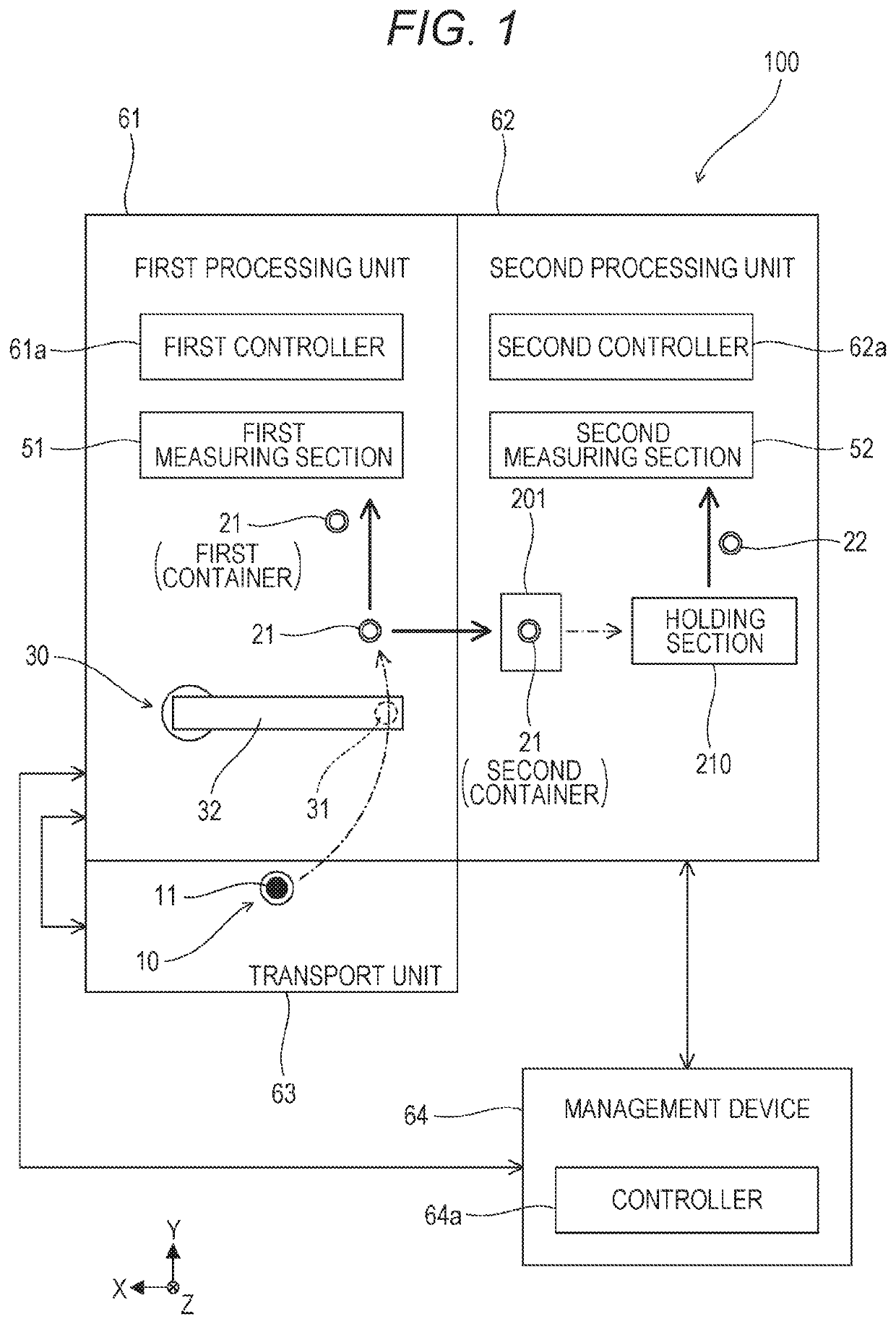
[0058]A sample measurement device 100 according to the present embodiment is a device that performs a first measurement and a second measurement in parallel. In recent years, various attempts have been made as a technique for examining a disease. As one of such techniques, a plurality of measurement results is combined. With this technique, a disease affecting the subject can be analyzed in more detail in some cases. For example, disseminated intravascular coagulation (DIC) can be appropriately diagnosed by combining a measurement result regarding a blood coagulation test and a measurement result regarding an immunological test. Specifically, the diagnosis of DIC is made on the basis of the coagulation time obtained from the measurement result regarding the blood coagulation test, and PIC, TAT, etc., obtained from the measurement result regarding the immunological test.

[0059]Hereinafter, the sample measurement device 100 that performs the first measurement related to the blood coagu...

second embodiment

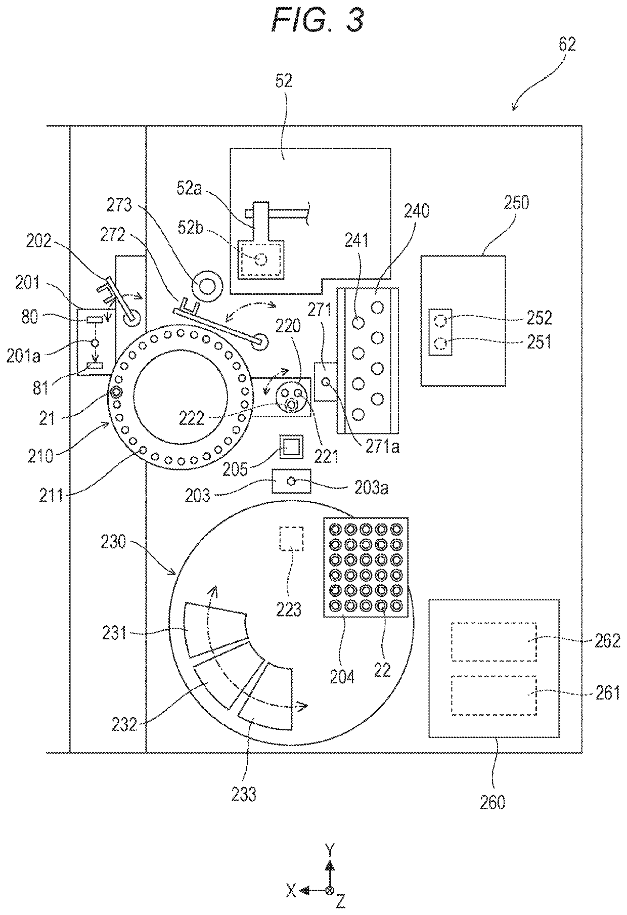
[0172]As shown in FIG. 10, a sample measurement device 100 according to the second embodiment transfers and receives the second container 21 between the first controller 61a and the second controller 62a via the relay section 201 without the intervention of the controller 64a of the management device 64.

[0173]A process of the sample measurement device 100 according to the second embodiment will be described with reference to FIGS. 8, 11A, and 11B. Steps S1 to S21 in the flowchart shown in FIG. 8 are the same as those in the first embodiment, and thus description thereof will be omitted.

[0174]As shown in FIG. 11A, when the controller 64a causes the first controller 61a to drive the dispensing section 30 to discharge the sample into the second container 21 in step S19 in FIG. 8, the processes similar to those in steps S101 and S102 in FIG. 9A are performed in steps S301 and S302.

[0175]In step S302, the reception of the second container 21 by the second processing unit 62 is completed,...

third embodiment

[0180]In the first and second embodiments, the detector 201b of the relay section 201, that is, the light receiver 81, is connected to only the second controller 62a. A sample measurement device 100 according to the third embodiment has a configuration in which the light receiver 81 is connected to both the first controller 61a and the second controller 62a.

[0181]As shown in FIG. 12, in the first processing unit 61, the first controller 61a is connected to the detector 201b of the relay section 201 in addition to the circuit configuration diagram shown in FIG. 6.

[0182]When the sample measurement device 100 is configured as described above, the signal of the light receiver 81 is output to both the first controller 61a and the second controller 62a. As described in the first embodiment, when the second container 21 is positioned in the relay section 201, the signal of the light receiver 81 falls to a low level, and when the second container 21 is transferred from the relay section 20...


PUM

PropertyMeasurementUnit
timeaaaaaaaaaa
timeaaaaaaaaaa
absorbanceaaaaaaaaaa

Abstract

Disclosed is a sample measurement device comprising a first processing unit that performs a first measurement on a sample contained in a first container in a first cycle; a second processing unit that performs a second measurement on a sample contained in a second container in a second cycle different from the first cycle; and a relay section which is disposed between the first processing unit and the second processing unit and in which the second container is positioned, wherein the first processing unit performs a transferring operation of transferring the second container to the relay section, and the second processing unit performs a receiving operation of receiving the second container that has been transferred to the relay section from the relay section.

Description

RELATED APPLICATIONS[0001]This application claims priority to Japanese Patent Application No. 2019-061846, filed on Mar. 27, 2019, the entire content of which is incorporated herein by reference.BACKGROUND OF THE INVENTION1. Field of the Invention[0002]The present invention relates to a sample measurement device and a sample measurement method for measuring a sample.2. Description of the Related Art[0003]Conventionally, a device for performing both biochemical measurement and blood coagulation measurement has been known, for example, as a device for analyzing an amount of components contained in a sample such as blood or urine. In an automatic analyzer 500 disclosed in US 2015104351, as shown in FIG. 14, when a biochemical measurement is performed, a sample is dispensed from a sample container 503 to a reaction cell 502 housed in a rotatable reaction disk 501, and then, a predetermined amount of reagent is dispensed from a first reagent disk 508 to the reaction cell 502, and the sam...

Claims


Application Information

Patent Timeline
Patent Type & Authority Applications(United States)
IPC IPC(8): G01N35/00G01N35/10G01N33/49G01N35/02
CPCG01N35/025G01N33/4905G01N35/1081G01N2035/00346G01N35/00871G01N35/1065G01N35/04G01N33/86G01N21/31G01N33/50G01N2035/0462G01N2035/0453G01N2035/0465G01N2035/00326
Inventor SHIBA, MASAKIKOTAKE, HIROKIKATO, AKIHITO
Owner SYSMEX CORP
Why Eureka
Try Eureka