Ellipitcal applicator system

a technology of elliptical applicator and vaginal cavity, which is applied in the field of elliptical applicator system, can solve the problems of involuntary urine loss, unnecessary discomfort of users, and elderly women, and achieve the effect of reducing friction

Inactive Publication Date: 2005-09-06
KIMBERLY-CLARK WORLDWIDE INC
View PDF70 Cites 29 Cited by
  • Summary
  • Abstract
  • Description
  • Claims
  • Application Information

AI Technical Summary

Benefits of technology

[0005]In one aspect of the present invention, an insert applicator includes an outer member adapted to house an insert, and an inner member moveable within the outer member and operable to discharge the insert from the outer member. The leading, vaginal insertion end portion of the out

Problems solved by technology

Some women, especially women who have given birth to one or more children, and older women, can experience incidences of involuntary urine loss due to stress urinary incontinence or combined stress and urge incontinence.
One challenge associated with the use of the inserts of the above mentioned patents and applications is that they are most effective when properly oriented within the vagina.
Furthermore, because

Method used


Image

  • Ellipitcal applicator system
  • Ellipitcal applicator system
  • Ellipitcal applicator system

Examples


Embodiment Construction

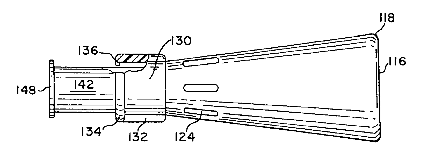
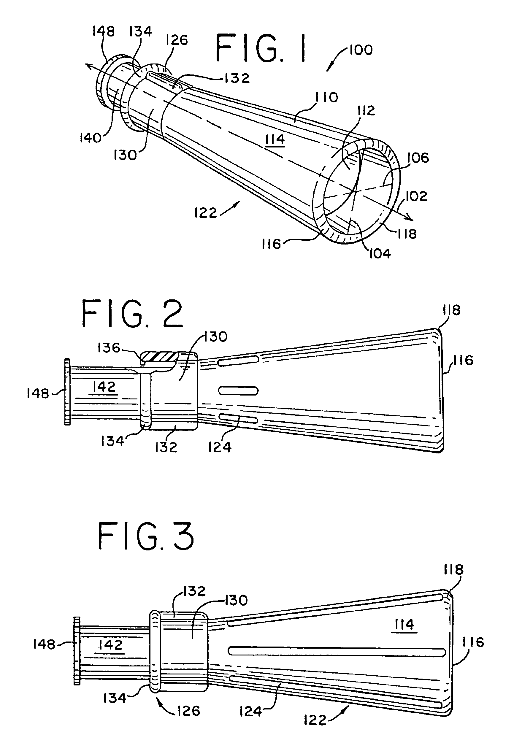
[0018]Referring now to the drawings and initially to FIG. 1, an insert applicator according to the present invention is shown generally at 100 in a pre-assembled configuration. The applicator 100 has an outer member or insert housing (or carriage) 110 and an inner member or plunger 140. The inner member 140 is slidably disposed within the outer member 110. The outer member 110 has a curved shape such as a cylinder, particularly a circle or ellipse and has an inner surface 112 and an outer surface 114. The outer member 110 extends along a longitudinal axis 102 from a leading, vaginal insertion end portion 116 to a trailing end portion 126. The outer member 110 houses an insert (not shown) that is to be discharged into the vaginal cavity.

[0019]Desirably, the outer member 110 includes a substantially cone-shaped portion 122 and a substantially cylindrical-shaped portion 130 extending substantially parallel to the longitudinal axis 102. In a direction substantially parallel to its longi...


PUM


Abstract

An applicator for placing an insert within a vagina. The insert can be a catamenial tampon, incontinence device, medicament, dressing, and the like. The applicator has orientation indicators to allow the user to properly orientate the insert within the vagina. The applicator also has an inwardly curved radius on the leading edge to reduce any resistance during insertion and withdrawal of the applicator. The applicator may also have at least one vent to facilitate expulsion of the insert or to deliver medicaments or lubricants inside the body cavity. The insert applicator has a rounded cross-section to maximize the available space for the insert, while also facilitating insertion of the applicator into the vagina.

Description

FIELD OF THE INVENTION[0001]The present invention relates generally to devices for delivering an insert into a body cavity, particularly a vagina and to methods for their use. The insert may be a catamenial tampon, incontinence device, medicament, dressing, or other similar inserts. The invention may find particular use for delivering inserts used to reduce the occurrence and / or severity of female urinary incontinence. More particularly, the present invention relates to an improved carriage for an applicator for delivering an incontinence device.BACKGROUND OF THE INVENTION[0002]Some women, especially women who have given birth to one or more children, and older women, can experience incidences of involuntary urine loss due to stress urinary incontinence or combined stress and urge incontinence. Accordingly, as the world's female population ages, there is an ever increasing need for a non-surgical procedure and / or device to reduce the involuntary urine loss commonly associated with “...

Claims


Application Information

Patent Timeline
IPC IPC(8): A61F13/20A61F13/26A61F13/28A61F2/00
CPCA61F2/005A61F13/26A61F13/28
Inventor ZUNKER, MARY ANNVELAZQUEZ, HERB F.SANDERS, DONALD J.PIERRON, JIM A.HECK, ANGELA R.
Owner KIMBERLY-CLARK WORLDWIDE INC
Why Eureka
Try Eureka