Electrical machine having a stator winding with a plurality of filars

Active Publication Date: 2005-09-06
BORGWARNER INC
View PDF27 Cites 23 Cited by
  • Summary
  • Abstract
  • Description
  • Claims
  • Application Information

AI Technical Summary

Benefits of technology

[0013]Also, the staggered pattern of the first and second filars of each phase reduces the amount of cross current circulation betwee

Problems solved by technology

These stators, however, are disadvantageous because the windings are typically interlaced, in which the wires are required to alternate outer and inner radial portions of each slot.
These interlaced windings require an interlacing process to interlace the conductors of all the phases prior to inserting the winding into the core or a connection process to connect the individual U-shaped conductors and therefore disadvantageously increase the complexity of placing the winding the stator.
However, bi-filar windings may be subject to overheating due to cross current circulation between filars.
However, some amount of the magnetic flux short circuits this path by prematurely crossing the slot before i

Method used


Image

  • Electrical machine having a stator winding with a plurality of filars
  • Electrical machine having a stator winding with a plurality of filars
  • Electrical machine having a stator winding with a plurality of filars

Examples


Embodiment Construction

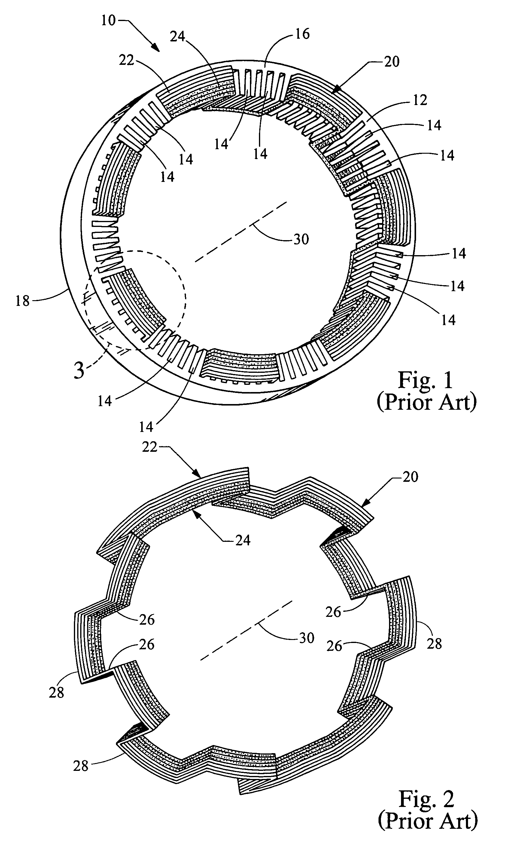
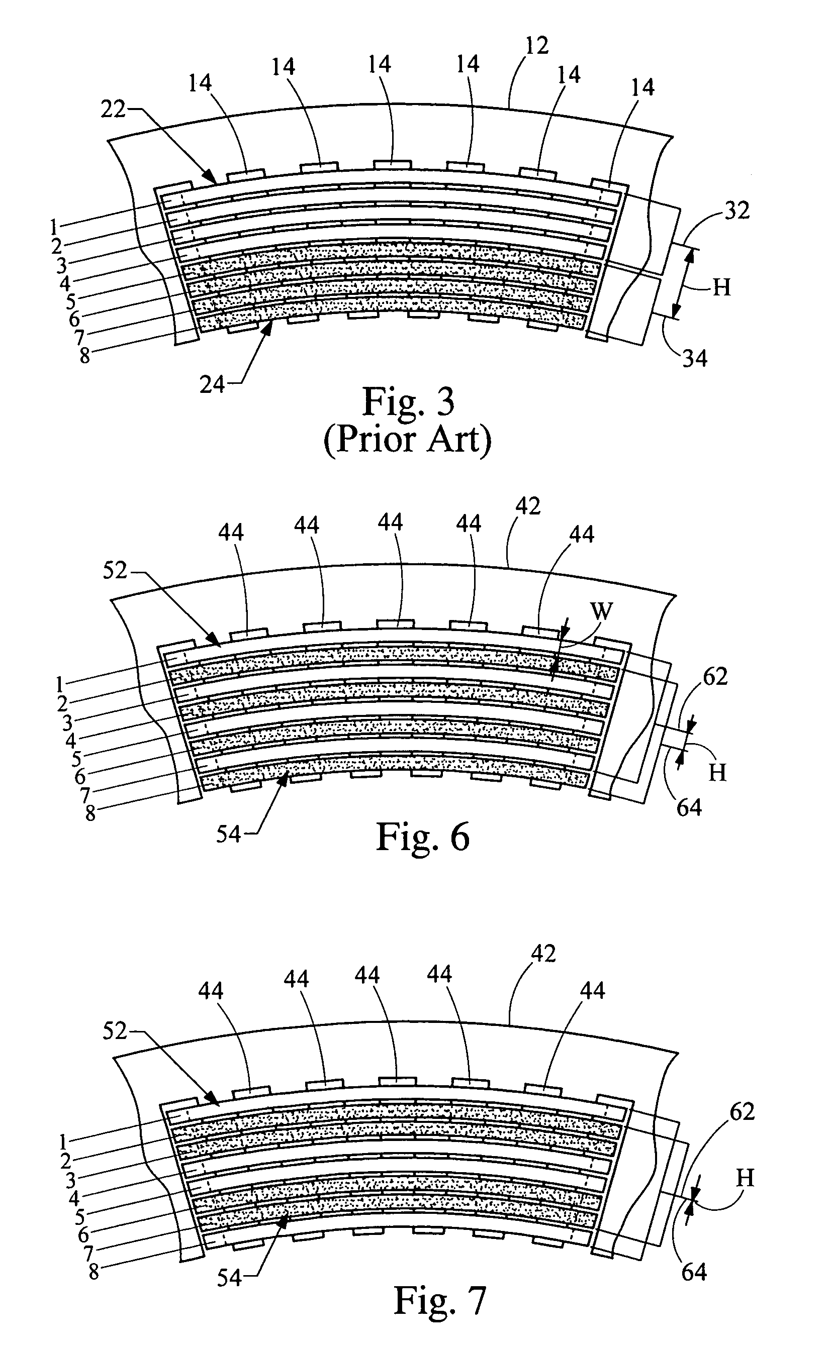
[0029]Referring now to FIGS. 1–3, a prior art stator is shown generally at 10. The stator 10 includes a generally cylindrically-shaped stator core 12 having a plurality of circumferentially spaced and axially-extending core slots 14. The core slots 14 define a plurality of teeth 15 there between, which are connected to one another by a yoke 19. The core slots 14 extend between a first end 16 of the stator core 12 and a second end 18 of the stator core 12. The stator core 12 includes a stator winding 20 having a plurality of phases (for simplicity, FIGS. 1–13 of stator winding 20 depict only one phase and do not show necessary end loop shapes that allow nesting of the end loops of all the phases, such as the cascade winding shown in FIGS. 17, 18, 19a and 19b). Each phase of the stator winding 20 comprises a first filar 22 and a second filar 24. As shown in FIGS. 1–3, as well as in FIGS. 4–13, the second filar 24 is indicated by stipple hatching. The first and second filars 22, 24 ext...


PUM


Abstract

A stator for an electric machine includes a generally cylindrically-shaped stator core having a plurality of circumferentially spaced core slots. A stator winding includes a plurality of phases, each including a plurality of filars, each filar extending circumferentially around the stator core to form a plurality of layers. Each of the filars is a conductor having a plurality of substantially straight segments disposed in the core slots. The straight segments are alternately connected at the first and second ends of the stator core by a plurality of end loop segments. The filars of a particular phase each have an average radial position within the stator core, and are staggered throughout the layers such that a distance between the average radial position of each filar and the average radial position of the other filars is minimized.

Description

BACKGROUND OF THE INVENTION[0001]The present invention relates generally to electric machines and, in particular, to a stator winding for an electric machine having a plurality of filars with reduced cross current circulation. Electric machines, such as alternating current electric generators, or alternators are well known. Prior art alternators typically include a stator assembly and a rotor assembly disposed in an alternator housing. The stator assembly is mounted to the housing and includes a generally cylindrically-shaped stator core having a plurality of slots formed therein. The rotor assembly includes a rotor attached to a generally cylindrical shaft that is rotatably mounted in the housing and is coaxial with the stator assembly. The stator assembly includes a plurality of wires wound thereon, forming windings. The stator windings are formed of straight portions that are located in the slots and end loop sections that connect two adjacent straight portions of each phase and ...

Claims


Application Information

Patent Timeline
IPC IPC(8): H02K3/28H02K3/04H02K3/12H02K19/34H02K19/36
CPCH02K3/14H02K3/28H02K19/34H02K19/36H02K1/12
Inventor CHEN, HANYANG BENNEET, KIRK E.
Owner BORGWARNER INC
Why Eureka
Try Eureka