Integrated circuit output driver circuitry with programmable preemphasis

a technology of output driver and integrated circuit, applied in the field of circuitry, can solve problems such as not providing programmable slope steepening effects

Active Publication Date: 2005-09-06
ALTERA CORP
View PDF33 Cites 73 Cited by
  • Summary
  • Abstract
  • Description
  • Claims
  • Application Information

AI Technical Summary

Problems solved by technology

The current supply circuitry in the preemphasis circuitry in this type of device is not programmable and the...

Method used


Image

  • Integrated circuit output driver circuitry with programmable preemphasis
  • Integrated circuit output driver circuitry with programmable preemphasis
  • Integrated circuit output driver circuitry with programmable preemphasis

Examples


Embodiment Construction

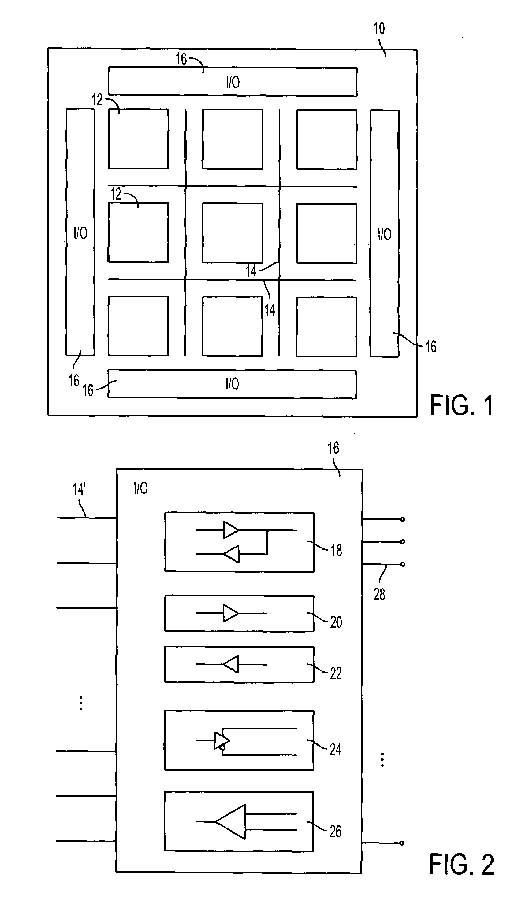
[0019]An illustrative programmable logic device 10 that can be constructed in accordance with this invention is shown in FIG. 1. Device 10 may have a number of rows and columns of regions 12 of programmable logic. Regions 12 may be disposed on device 10 in a two-dimensional array of, for example, 5–300 rows and 5–300 columns of regions 12 or any other suitably-sized array.

[0020]The logic in regions 12 may be interconnected using interconnection resources such as vertical and horizontal conductors 14. Such conductors may, for example, include relatively large inter-region conductors that extend past all or some of the logic regions 12 in a row or column. There may be any suitable number of conductors 14. For example, there may be about 10–30 conductors 14 in each row and each column of regions 12. Programmable logic may be used to selectively connect all or a subset of the conductors 14 in each row or column to the associated logic regions 12 in that column. If desired, programmable ...


PUM


Abstract

Programmable logic device integrated circuitry having differential I/O circuitry is provided. The differential I/O circuitry may include output drivers for providing differential digital output data signals across pairs of output lines. A user may program the I/O circuitry to accommodate different high-speed differential I/O signaling standards. The user may also program the I/O circuitry to provide a desired amount of preemphasis to the output data signals.

Description

BACKGROUND OF THE INVENTION[0001]This application relates to circuitry for integrated circuits such as programmable logic array integrated circuits (“programmable logic devices”), and more particularly, to programmable output driver circuitry with the capability to provide adjustable amounts of preemphasis.[0002]Programmable logic devices are integrated circuits that may be programmed by a user to perform various logic functions. Programmable logic devices may have differential (two-pin) input-output (“I / O”) circuitry for handling high-speed (I / O) signals. Some currently-available programmable logic devices with differential input-output circuitry use output drivers with a fixed (non-programmable) preemphasis feature and have input-output driver circuitry that may be selectively configured to accommodate different communications standards. The preemphasis capabilities that are provided by these output drivers help to drive high-speed signals over communications paths that are used t...

Claims


Application Information

Patent Timeline
IPC IPC(8): H03K19/177H03K19/0185H04L25/02
CPCH03K19/018585H03K19/17744H03K19/1778H04L25/0286H04L25/0272
Inventor SHUMARAYEV, SERGEY Y.WHITE, THOMAS H.PATEL, RAKESH H.WONG, WILSON
Owner ALTERA CORP
Why Eureka
Try Eureka