Circuit arrangement and method for deriving electrical power from an electromagnetic field

ircuit arrangement technology, applied in the field of circuit arrangement and a method for deriving or extracting electrical power from a high frequency electromagnetic field, can solve the problems of destroying the rectifier requiring a large or large real part of the input impedance, and destroying the rectifier itself or other circuit components, so as to prevent the destruction, damage or failure of circuit components.

Active Publication Date: 2005-09-06
ATMEL GERMANY +1
View PDF30 Cites 53 Cited by
  • Summary
  • Abstract
  • Description
  • Claims
  • Application Information

AI Technical Summary

Benefits of technology

[0012]In view of the above, it is an object of the invention to provide a circuit arrangement and a method for deriving or extracting electrical power from a received electromagnetic field, e.g. the electromagnetic field emitted by a base station, so as to reliably provide a sufficient voltage supply even in the far field region of the electromagnetic field, yet limit the power take-up in the near field or close range of the electromagnetic field, so as to prevent destruction, damage or failure of circuit components due to excessive power or voltage. A further, more particular object of the invention is to adjust or vary the power take-up from the received field depending on the field strength prevailing at the antenna. The invention further aims to avoid or overcome the disadvantages of the prior art, and to achieve additional advantages, as apparent from the present specification. The attainment of these objects is, however, not a required limitation of the invention.
[0014]The above objects have further been achieved according to the invention in a method of deriving electrical power from a received high frequency electromagnetic field, which method may be carried out with the inventive circuit arrangement. The method involves varying the impedance, and particularly predominantly the imaginary part of the input impedance, of at least one circuit component of the detuning unit depending on the field strength of the electromagnetic field prevailing at the antenna. This consequently allows the degree of tuning or impedance matching of the input circuit and the antenna to be adjusted or varied, so that a sufficient amount of power can still be absorbed (by using a high degree of matching) when the field strength is low, while avoiding excessive power absorption (by using a low degree of matching, or thus mis-matching) when the field strength is high.
[0016]On the other hand, when the field strength of the electromagnetic field prevailing at the antenna sharply increases in the near field region of the base station, then the impedance of the pertinent circuit component of the transponder will vary sharply, whereby the resulting input impedance of the circuit portion of the transponder connected to the antenna will similarly be sharply varied. Particularly, this achieves a relatively strong mis-matching of the antenna, and consequently a sharp reduction of the power coupled out of the electromagnetic field via the antenna into the input circuit portion of the transponder. Thereby, an excessive power delivery to connected circuit components, such as a rectifier, is prevented. In contrast, as explained above, when operating in the far field region with a relatively low field strength, the antenna is operated in a matched or tuned manner so that the maximum power derivable from the prevailing electromagnetic field is made available for the connected circuit components.
[0017]Such a realization of the detuning is able to achieve a sharp variation of both the real part and the imaginary part of the input impedance dependent on the input power. Therefore, the inventive detuning achieves a considerably more effective power reduction in connection with an increasing available input power (corresponding to an increasing field strength), in comparison to an ASK based detuning unit. Particularly, this is because the invention involves changing or altering both the real part as well as the imaginary part (and especially predominantly the imaginary part) of the input impedance, in contrast to the ASK based detuning unit which varies essentially only the real part of the impedance. The invention thus allows the modulator or the load resistor used for the ASK process to be omitted, and the related disadvantages thereof to be avoided, namely that the parasitic characteristics of the ASK modulator or load resistance, when arranged in the input portion, have a negative influence on the effectiveness of the input portion, and when arranged at the output of a rectifier, cause an impairment of the far field characteristics. Furthermore, a regulator for activating and controlling the ASK modulator, for setting a suitable mis-match or detuning dependent on the power being supplied or fed-in, is similarly not necessary in the inventive circuit arrangement. Overall, these features of the invention lead to a simplified design, a reduction of the required chip surface area, reduced costs, and significantly increased operational security and reliability.
[0020]In a further embodiment of the circuit arrangement according to the invention, the circuit component of the detuning unit is a varactor, especially a varactor or varactor diode with a high quality factor. This is advantageous because varactors are relatively simple to realize and to integrate into circuit arrangements, and inherently have a voltage-dependent capacitance. Thus, such a varactor, if properly arranged and dimensioned, can “automatically” (without any additional active control device) provide the required inventive variation of the impedance responsive to and dependent on the input voltage, which relates to the field strength coupled into the input circuit. Alternatively, the varactor can be actively controlled to vary the impedance by applying thereto a control voltage that depends on the field strength of the electromagnetic field prevailing at the antenna. Due to the high quality factor, i.e. a relatively low ohmic resistive component of the impedance, the power dissipation caused by the circuit component is minimized.
[0023]In a further embodiment of the circuit arrangement according to the invention, a rectifier is connected to the terminals of the antenna, and a voltage limiter circuit is coupled to the output of the rectifier. This voltage limiter circuit may, for example, be in the form of plural diodes connected in series. This voltage limiter circuit provides an additional protection against excessive voltages being produced at the output of the rectifier, and achieves an increased operating security and reliability, and an increased protection against destruction or damage of the circuit components.

Problems solved by technology

The corresponding high sensitivity of the rectifier that is required in this regard may, however, lead to destruction of the rectifier itself or other circuit components when the transponder operates in the near field or close range of the base station, due to the higher field strength of the emitted electromagnetic field prevailing there.
Namely, the higher received field strength may, for example, cause the rectifier to generate an output voltage that is too high, so that it must necessarily be limited by a voltage regulator.
Depending on the particular design or embodiment of the voltage regulator, this can lead to an increased current flow in the rectifier, which may cause the generated or dissipated power to exceed the maximum permissible power and thereby may destroy the rectifier or other circuit components.
Such a known detuning by means of ASK modulation, however, requires a high or large real part of the input impedance in comparison to the imaginary part thereof.
In view of the above, problems or difficulties arise if such a detuning is to be used in connection with a phase shift keying (PSK) modulation for carrying out the data transmission between the transponder and the base station.
Such low resistance switching devices generally comprise relatively large parasitics, which lead to corresponding losses in normal operation, whereby the transmission range of the transponder is correspondingly reduced.
For this reason, it is generally not possible to combine a PSK modulator for carrying out a PSK modulation for the data transmission, with a detuning unit based on varying the real part of the input impedance, i.e. based on an ASK modulation.
In this context, the diodes become conductive when, for example due to an ESD interference, an unusually high and interfering input voltage exceeds a diode threshold voltage of the diodes.

Method used


Image

  • Circuit arrangement and method for deriving electrical power from an electromagnetic field
  • Circuit arrangement and method for deriving electrical power from an electromagnetic field
  • Circuit arrangement and method for deriving electrical power from an electromagnetic field

Examples


Embodiment Construction

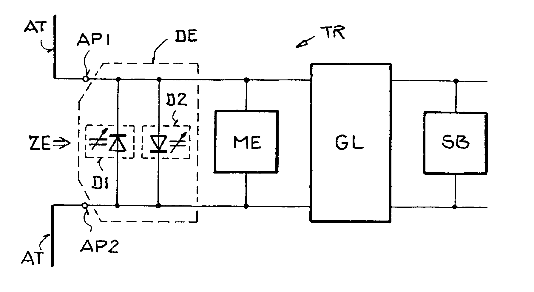
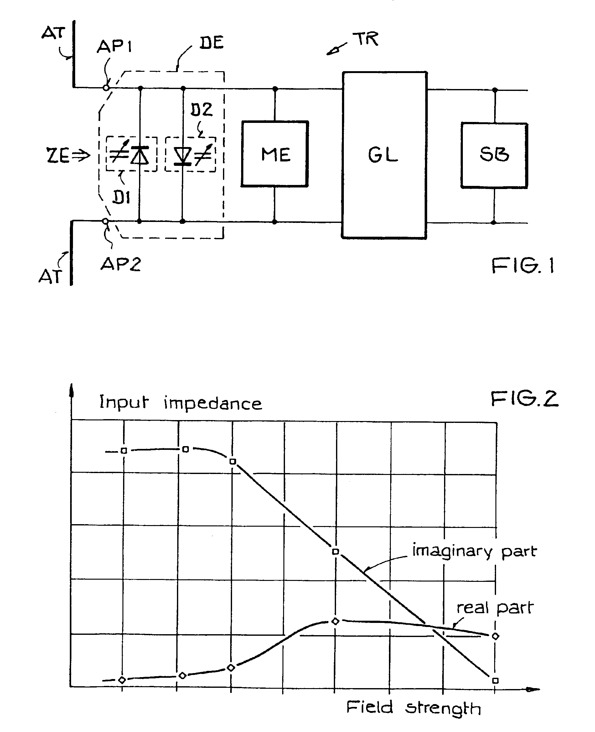
[0030]The schematic block circuit diagram of FIG. 1 shows a circuit arrangement for deriving electrical power from a received electromagnetic field, whereby this circuit arrangement is integrated into a passive transponder TR. The overall or other circuitry of the transponder TR (not shown in detail) may be according to any conventionally known circuit arrangements of passive transponders, remote sensors, or the like.

[0031]The illustrated embodiment of the inventive circuit arrangement comprises an antenna AT having two connection poles or terminals AP1 and AP2, a detuning unit DE, a modulation arrangement or modulator ME, a rectifier GL, and a voltage limiter SB. The detuning unit DE, the modulator ME and the rectifier GL are each directly connected in succession to the two antenna terminals AP1 and AP2. Being “directly” connected means connected with only conductors therebetween and without any other circuit components interposed therebetween. The voltage limiter SB is connected t...


PUM


Abstract

A circuit arrangement for deriving electrical power from a received electromagnetic field to power a transponder includes a detuning unit connected between two antenna terminals for limiting the power absorbed by the antenna. The detuning unit includes a component having an impedance that passively varies or is actively varied dependent on the field strength of the field prevailing at the antenna. One arrangement of the detuning unit includes two varactor diodes connected anti-parallel between the antenna terminals. Another arrangement of the detuning unit includes a varactor arranged in series between two capacitors between the antenna terminals, a field strength detector, and a controllable voltage source connected to apply to the varactor a control voltage that varies depending on the detected field strength. Thereby, the input impedance varies depending on the field strength, to achieve impedance matching for a low field strength, and a mis-matched condition for a high field strength.

Description

PRIORITY CLAIM[0001]This application is based on and claims the priorities under 35 U.S.C. §119 of German Patent Applications 103 01 452.7 filed on Jan. 10, 2003 and 103 57 665.7 filed on Dec. 4, 2003, the entire disclosures of which are incorporated herein by reference.FIELD OF THE INVENTION[0002]The invention relates to a circuit arrangement and a method for deriving or extracting electrical power from a high frequency electromagnetic field, especially such a field that has been emitted by a base station and received by a transponder that modulates and backscatters or reflects the received electromagnetic waves. The transponder may especially be a passive transponder operating only on the electrical power derived from the received field.BACKGROUND INFORMATION[0003]Circuit arrangements of the above mentioned general type are used, for example, in transponders for wireless or contactless identification systems such as RFID systems (radio frequency identification systems) and in remo...

Claims


Application Information

Patent Timeline
Patent Type & Authority Patents(United States)
IPC IPC(8): G06K19/07H02J17/00H04B1/59
CPCG06K19/0701G06K19/0723H04B5/0075
Inventor FISCHER, MARTINFRIEDRICH, ULRICHKARTHAUS, UDO
Owner ATMEL GERMANY
Why Eureka
Try Eureka