[0014] The above objects have further been achieved according to the invention in a method of deriving electrical power from a received
high frequency electromagnetic field, which method may be carried out with the inventive circuit arrangement. The method involves varying the impedance, and particularly predominantly the imaginary part of the input impedance, of at least one circuit component of the detuning unit depending on the field strength of the electromagnetic field prevailing at the antenna. This consequently allows the degree of tuning or
impedance matching of the input circuit and the antenna to be adjusted or varied, so that a sufficient amount of power can still be absorbed (by using a high degree of matching) when the field strength is low, while avoiding excessive
power absorption (by using a low degree of matching, or thus mis-matching) when the field strength is high.
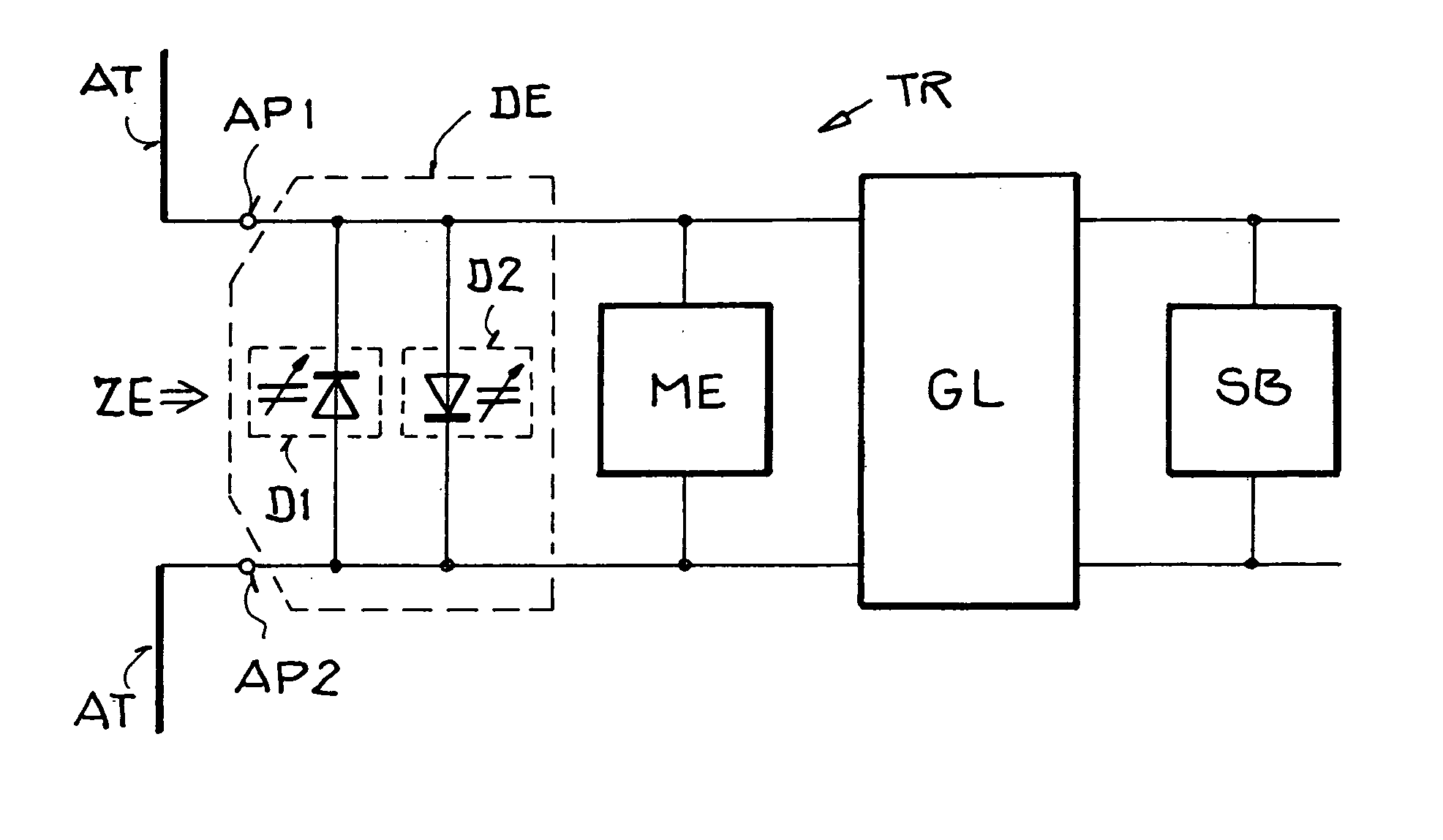
[0016] On the other hand, when the field strength of the electromagnetic field prevailing at the antenna sharply increases in the near field region of the base
station, then the impedance of the pertinent circuit component of the transponder will vary sharply, whereby the resulting input impedance of the circuit portion of the transponder connected to the antenna will similarly be sharply varied. Particularly, this achieves a relatively strong mis-matching of the antenna, and consequently a sharp reduction of the power coupled out of the electromagnetic field via the antenna into the input circuit portion of the transponder. Thereby, an excessive power delivery to connected circuit components, such as a rectifier, is prevented. In contrast, as explained above, when operating in the far field region with a relatively low field strength, the antenna is operated in a matched or tuned manner so that the maximum power derivable from the prevailing electromagnetic field is made available for the connected circuit components.
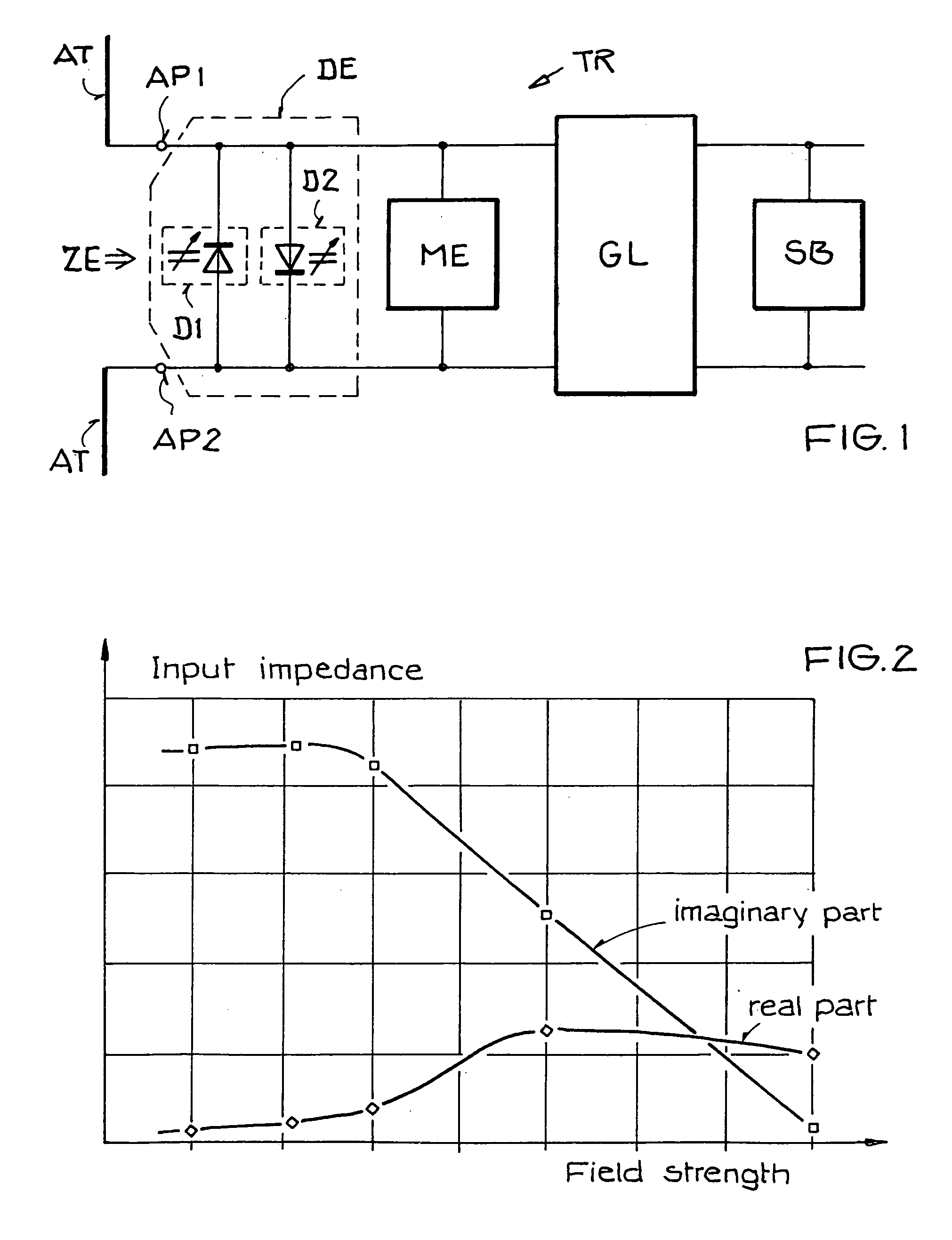
[0017] Such a realization of the detuning is able to achieve a sharp variation of both the real part and the imaginary part of the input impedance dependent on the input power. Therefore, the inventive detuning achieves a considerably more
effective power reduction in connection with an increasing available input power (corresponding to an increasing field strength), in comparison to an ASK based detuning unit. Particularly, this is because the invention involves changing or altering both the real part as well as the imaginary part (and especially predominantly the imaginary part) of the input impedance, in contrast to the ASK based detuning unit which varies essentially only the real part of the impedance. The invention thus allows the modulator or the load
resistor used for the ASK process to be omitted, and the related disadvantages thereof to be avoided, namely that the parasitic characteristics of the ASK modulator or
load resistance, when arranged in the input portion, have a negative influence on the effectiveness of the input portion, and when arranged at the output of a rectifier, cause an impairment of the far field characteristics. Furthermore, a
regulator for activating and controlling the ASK modulator, for setting a suitable mis-match or detuning dependent on the power being supplied or fed-in, is similarly not necessary in the inventive circuit arrangement. Overall, these features of the invention lead to a simplified design, a reduction of the required
chip surface area, reduced costs, and significantly increased operational security and reliability.
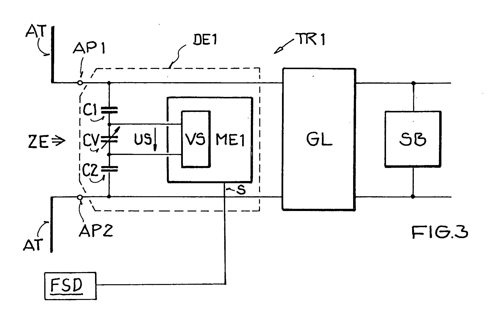
[0020] In a further embodiment of the circuit arrangement according to the invention, the circuit component of the detuning unit is a varactor, especially a varactor or varactor
diode with a high quality factor. This is advantageous because varactors are relatively simple to realize and to integrate into circuit arrangements, and inherently have a voltage-dependent
capacitance. Thus, such a varactor, if properly arranged and dimensioned, can "automatically" (without any additional
active control device) provide the required inventive variation of the impedance responsive to and dependent on the input voltage, which relates to the field strength coupled into the input circuit. Alternatively, the varactor can be actively controlled to vary the impedance by applying thereto a control voltage that depends on the field strength of the electromagnetic field prevailing at the antenna. Due to the high quality factor, i.e. a relatively low ohmic resistive component of the impedance, the power dissipation caused by the circuit component is minimized.
[0023] In a further embodiment of the circuit arrangement according to the invention, a rectifier is connected to the terminals of the antenna, and a voltage
limiter circuit is coupled to the output of the rectifier. This voltage
limiter circuit may, for example, be in the form of plural diodes connected in series. This voltage
limiter circuit provides an additional protection against excessive voltages being produced at the output of the rectifier, and achieves an increased operating security and reliability, and an increased protection against destruction or damage of the circuit components.

