Method for establishing a route via a communications network

a communication network and route technology, applied in data switching networks, time-division multiplexing selection, digital transmission, etc., can solve the problem of reducing the memory capacity required in the network node, and achieve the effect of reducing the memory capacity required

Inactive Publication Date: 2005-09-06
UNIFY GMBH & CO KG
View PDF9 Cites 10 Cited by
  • Summary
  • Abstract
  • Description
  • Claims
  • Application Information

AI Technical Summary

Benefits of technology

[0017]A critical advantage of the invention is that, in contrast to the prior art wherein switching information for all network nodes arranged in the communication network are stored in a network node in the present invention, only those switching information are stored in the network nodes of the communication network that are required for the connections currently conducted over the network node. This leads to a considerable reduction of the memory capacity required in the network node.
[0018]Another advantage of the invention is that, given the present method for route determination and in contrast to the signaling in a connection-oriented communication network, no transmission conditions such as, for example, a declaration about the required transmission capacity or about real-time demands are made, so that a route determination and a subsequent message communication can be realized faster.
[0019]In another embodiment of the of the invention wherein a connection setup message or, a confirmation message is not forwarded up to the originating or, destination communication terminal device participating in a connection but is processed in the network node allocated to the originating or, destination communication terminal device. This has the advantage that the source or, the destination communication terminal device can be kept free of routing jobs.
[0020]One other advantage of developments of the invention is that a decision about the selection of a route between a source communication terminal device and a destination communication terminal device can be made by the subscriber at the destination communication terminal device, so that the criteria for a connection setup relevant to said subscriber such as, for example, the transmission time, the costs or the transmission capacity made available on the identified route take effect.
[0021]As a result of a deletion of switching information stored in a network node after expiration of a prescribable time span (for example, after 10 minutes) wherein no messages allocated to these switching information were communicated, assures that only the currently acquired switching information are stored in a network node.

Problems solved by technology

This leads to a considerable reduction of the memory capacity required in the network node.

Method used


Image

  • Method for establishing a route via a communications network
  • Method for establishing a route via a communications network
  • Method for establishing a route via a communications network

Examples


Embodiment Construction

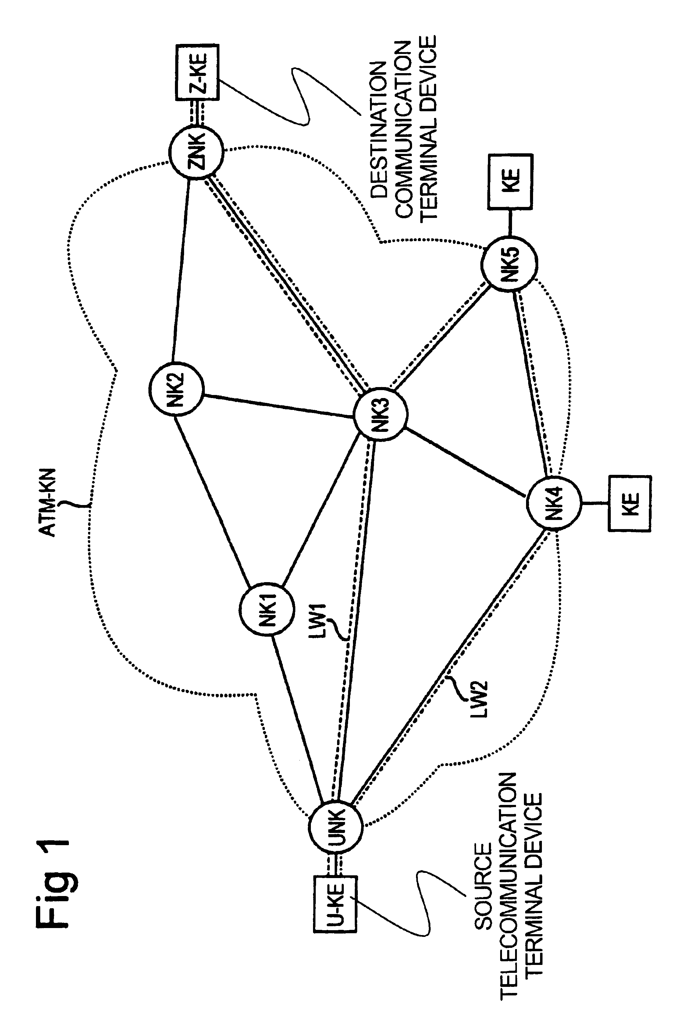
[0026]FIG 1. shows a schematic illustration of an ATM-based communication network ATM-KN having network nodes NK arranged therein and connected to one another. FIG. 1 shows five network nodes, NK1 through NK5. The network nodes NK are realized, for example, by ATM switching systems to which communication terminal devices can be connected. By way of example, two communication terminal devices KE are shown that are connected via a fourth network node NK4 or, respectively, via a fifth network node NK5 to the ATM-based communication network ATM-KN.

[0027]Further, a source communication terminal device U-KE is connected to the ATM-based communication network ATM-KS via a network node NK—referred to as source network node UNK below—and a destination communication terminal device Z-KE is connected to the ATM-based communication network ATM-KN via a further network node NK—referred to below as destination network node ZNK.

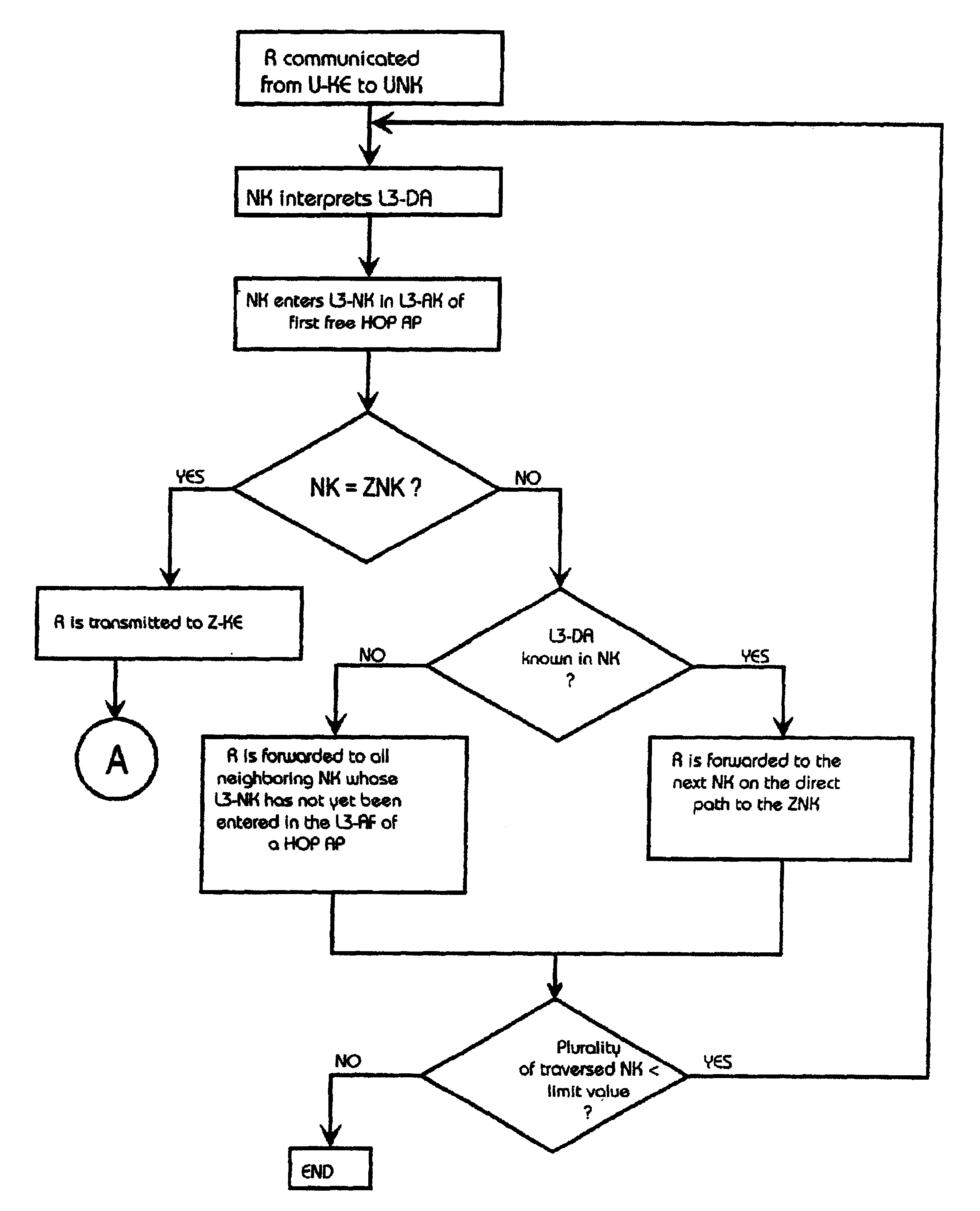
[0028]Proceeding from the source communication terminal device U-KE, a...


PUM


Abstract

Proceeding from a source terminal device a connection setup message is communicated to a network node of the communication network A network node receiving the connection setup message enters the network node address allocated to it in the communication network and forwards the connection setup message to at least one neighboring network node. Upon reception of the connection setup message at a destination terminal device, a confirmation message is returned to the source terminal device on the identified route, whereby a switching information for a following message transmission is stored in the network nodes that have been traversed.

Description

BACKGROUND OF THE INVENTION[0001]1. Field of the Invention[0002]The present invention is directed to a method for establishing a route via a communication network comprising a plurality of network nodes connected to one another.[0003]2. Description of the Related Art[0004]In communication networks, a distinction is made between connectionless and connection-oriented communication networks dependent on the topology of the communication networks. In connectionless communication networks, a signalling phase preceding a message transmission between comm terminal devices allocated to the communication network is omitted, a communication connection between the communication terminal devices being set up in the framework of said signalling phase. In the framework of the signalling phase, a layer-3 connection (switching layer) is established according to the OSI reference model (Ōpen {overscore (S)}ystems Īnterconnection), i.e. the communication connection between the communication terminal...

Claims


Application Information

Patent Timeline
Patent Type & Authority Patents(United States)
IPC IPC(8): H04L12/56H04Q11/04H04L12/70H04L12/701
CPCH04L45/00H04Q11/0478H04L2012/562
Inventor HUNLICH, KLAUS
Owner UNIFY GMBH & CO KG
Why Eureka
Try Eureka