Fiber optic cable having no rigid strength members and a reduced coefficient of thermal expansion

a fiber optic cable and rigid strength technology, applied in the field of fiber optic cables, can solve the problems of significantly limited bending performance of fiber optic cables and negatively affect the installation ease of conventional fiber optic cables, and achieve the effects of reducing the coefficient of thermal expansion, rigid strength members, and reducing size and weigh

Inactive Publication Date: 2005-09-06
DRAKA COMTEQ BV
View PDF9 Cites 146 Cited by
  • Summary
  • Abstract
  • Description
  • Claims
  • Application Information

AI Technical Summary

Benefits of technology

[0008]A fiber optic cable is provided with an outer jacket material having a coefficient of thermal expansion less than approximately 6E−5 in the range from 23° C. to −50° C. By utilizing an outer jacket m

Problems solved by technology

While the rigid strength members are effective in reducing the thermal contraction of the cable, the use of rigid strength members introduces numerous drawbacks.
Another drawback associated with the use of ri

Method used


Image

  • Fiber optic cable having no rigid strength members and a reduced coefficient of thermal expansion
  • Fiber optic cable having no rigid strength members and a reduced coefficient of thermal expansion
  • Fiber optic cable having no rigid strength members and a reduced coefficient of thermal expansion

Examples


Embodiment Construction

[0014]The following description of illustrative non-limiting embodiments of the invention discloses specific configurations, features, and operations. However, the embodiments are merely examples of the present invention, and thus, the specific features described below are merely used to more easily describe such embodiments and to provide an overall understanding of the present invention.

[0015]Accordingly, one skilled in the art will readily recognize that the present invention is not limited to the specific embodiments described below. Furthermore, the description of various configurations, features, and operations of the present invention that are known to one skilled in the art are omitted for the sake of clarity and brevity. Also, it is to be understood that the phraseology and terminology employed herein is for the purpose of description and should not be regarded as limiting.

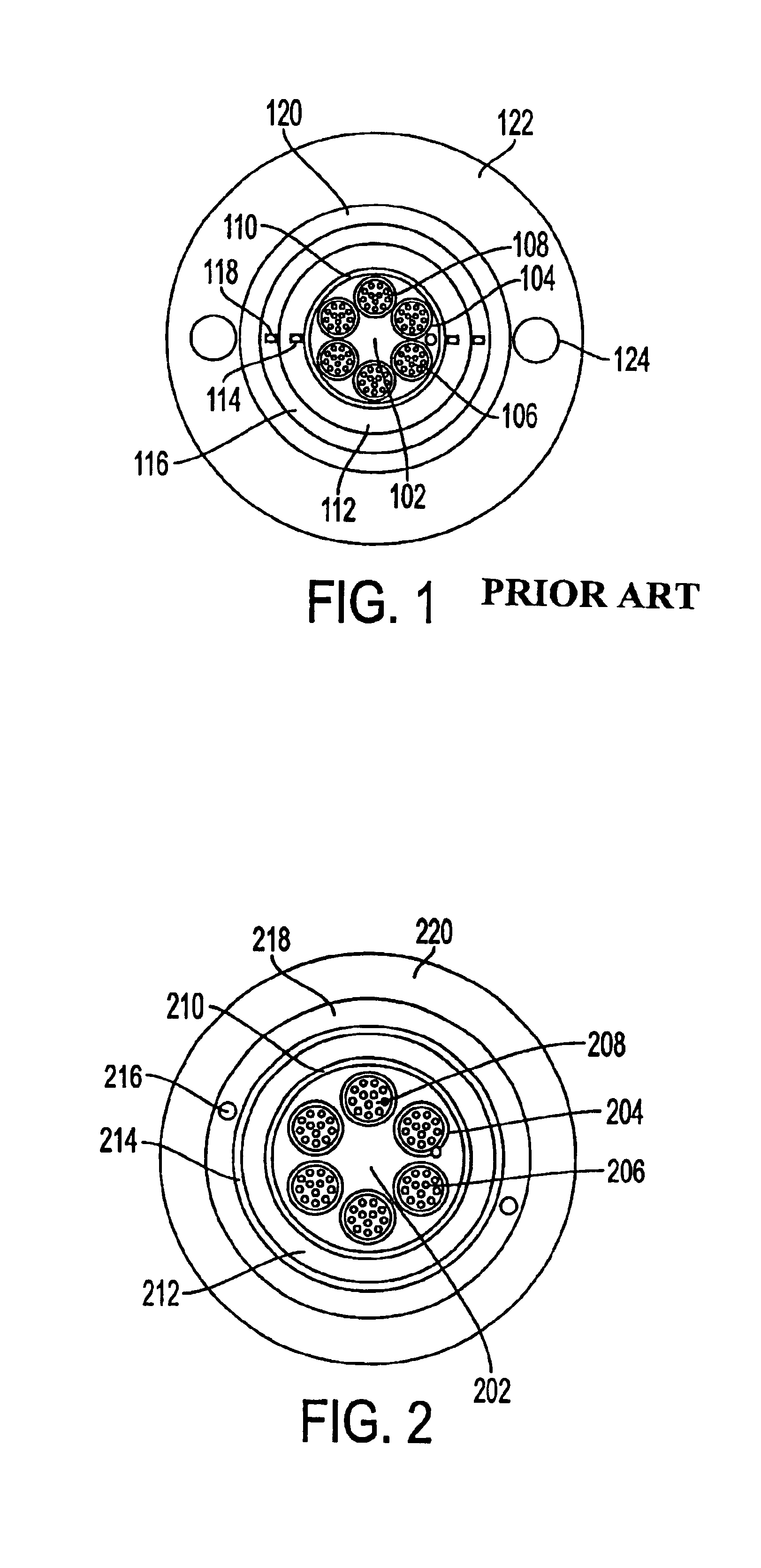
[0016]FIG. 1 shows a cross-sectional view of a conventional fiber optic cable. The cable is provided w...


PUM


Abstract

A fiber optic cable is provided with an outer jacket material having a coefficient of thermal expansion less than approximately 6E−5 in the range from 23° C. to −50° C. By utilizing an outer jacket material having a reduced coefficient of thermal expansion, the need for rigid strength members within the outer jacket is eliminated, thereby providing a fiber optic cable having a reduced size and weight.

Description

BACKGROUND OF THE INVENTION[0001]1. Field of the Invention[0002]The present invention relates generally to a fiber optic cable. More particularly, the present invention relates to a fiber optic cable having no rigid strength members, a reduced weight, and a reduced coefficient of thermal expansion.[0003]2. Related Art[0004]A conventional central tube fiber optic cable design includes rigid strength members embedded in an outer jacket of the cable. The rigid strength members are utilized for tensile strength and to prevent attenuation in the optical fibers within the cable due to thermal contraction of the cable.[0005]While the rigid strength members are effective in reducing the thermal contraction of the cable, the use of rigid strength members introduces numerous drawbacks. For example, the presence of rigid strength members in the outer jacket significantly increases the wall thickness of the outer jacket, the overall diameter of the fiber optic cable, and the weight of the fiber...

Claims


Application Information

Patent Timeline
IPC IPC(8): G02B6/44
CPCG02B6/443
Inventor RISCH, BRIANSTORAASLI, OLAF
Owner DRAKA COMTEQ BV
Why Eureka
Try Eureka