Microphone position and speech level sensor

a microphone and speech level technology, applied in the field of proper operation, can solve the problems of low insufficient quality at the user side of the telephone call, weak voice signal, etc., and achieve the effect of signal-to-noise ratio of voice signal at the microphon

Active Publication Date: 2005-09-06
PLANTRONICS
View PDF19 Cites 71 Cited by
  • Summary
  • Abstract
  • Description
  • Claims
  • Application Information

AI Technical Summary

Benefits of technology

[0015]The second threshold is used to determine whether the voice signal is too weak. This second threshold represents levels that are ordinarily attained only by speech at adequate levels. A second comparator receives a voice signal from the microphone and compares it to the second threshold. If speech peaks within the voice signal are consistently stronger than the second threshold, then the microphone is properly positioned. If the voice signal is weaker than or equal to the second threshold, then the signal-to-noise ratio of the voice signal at the microphone is too low to provide sufficient quality at a user side of the telephone call. Either a microphone being mispositioned or a user talking too quietly typically causes this weak voice signal.

Problems solved by technology

If the voice signal is weaker than or equal to the second threshold, then the signal-to-noise ratio of the voice signal at the microphone is too low to provide sufficient quality at a user side of the telephone call.
Either a microphone being mispositioned or a user talking too quietly typically causes this weak voice signal.

Method used


Image

  • Microphone position and speech level sensor
  • Microphone position and speech level sensor
  • Microphone position and speech level sensor

Examples


first embodiment

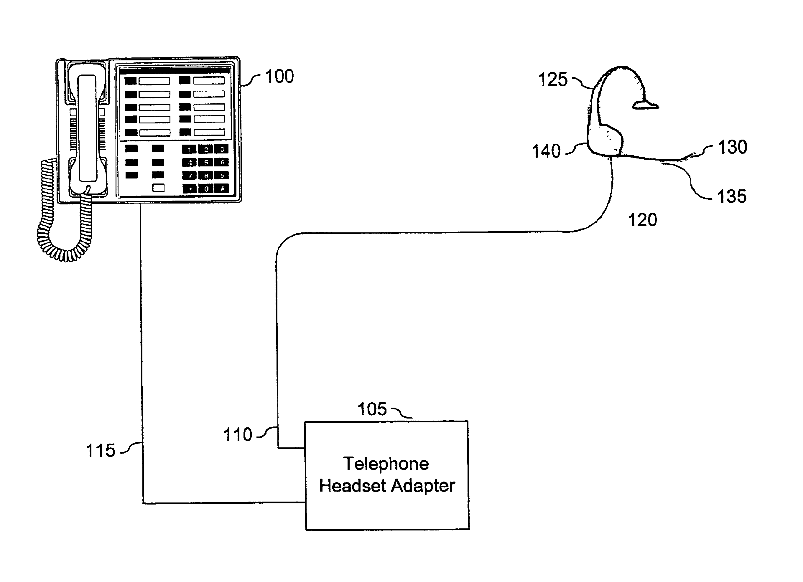
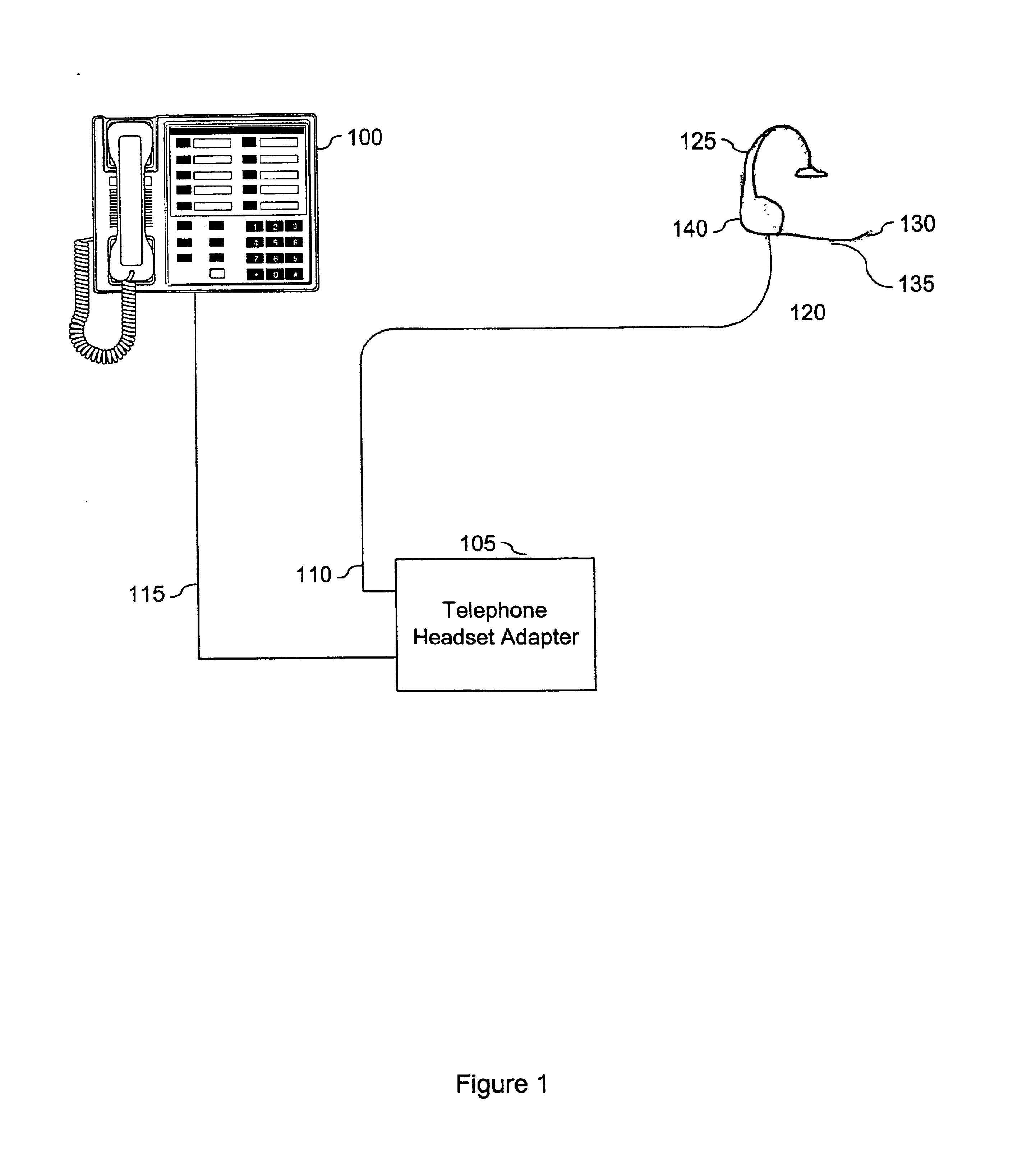
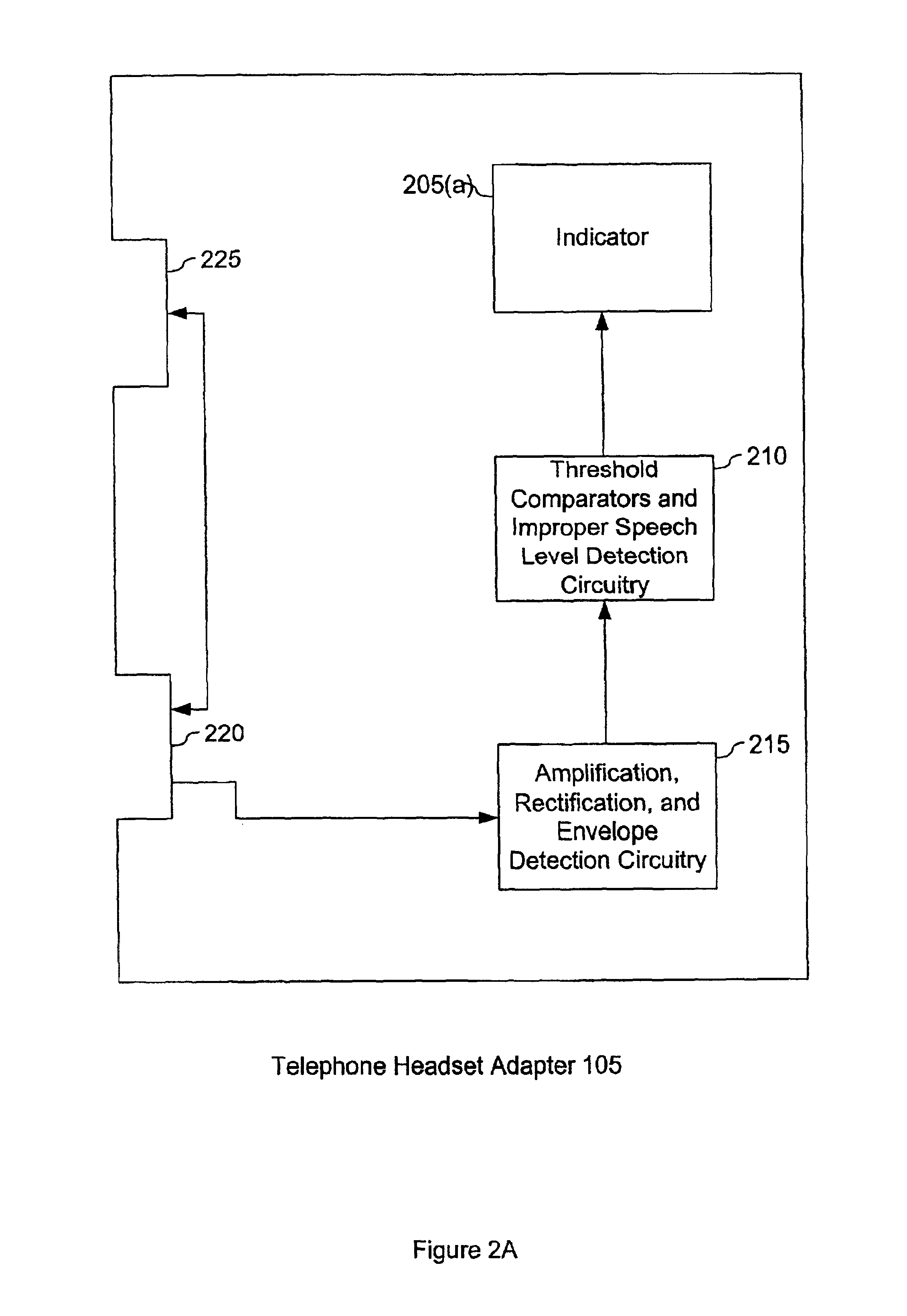
[0034]FIG. 2A shows the present invention functioning within a telephone adapter 105. As shown, a telephone adapter 105 contains at least two interfaces. A first interface 220 connects a telephone headset 120 to amplification, rectification and envelope detection circuitry 215 within the telephone adapter 105. An example of a first interface 220 is a telephone jack that allows a telephone headset line to plug into the telephone adapter 105 and communicate with the amplification, rectification and envelope detection circuitry 215. The first interface 220 may include other types of connection interfaces that allow data to be transmitted between the telephone headset 120 and the telephone adapter 105 such as a wireless transceiver. The first interface 220 is also coupled to a second interface 225 that connects the telephone adapter 105 to the telephone 100. This second interface 225 is generally a telephone jack or other hard-wire connection.

[0035]The amplification, rectification and e...

second embodiment

[0039]FIG. 2B shows the present invention whereby an indicator 205(b) is external to the telephone adapter 105. As shown, the telephone adapter 105 includes a third interface 230. The third interface 230 couples the external indicator 205(b) to the improper speech level detection circuitry 210 within the telephone adapter 105. Examples of the third interface 230 include a fixed line connection whereby the external indicator 205b is electrically coupled to the improper speech level detection circuitry 210, and a plug in jack (e.g., mini-8) whereby the indicator 205(b) may be attached or removed by connecting a plug into the third interface 230. Additionally, the third interface 230 may be a transceiver that transmits a wireless signal to the external indicator 205(b).

[0040]The threshold comparators and the improper speech level detection circuitry 210 activates the external indicator 205(b) via the third interface 230. Examples of the external indicator include a light (e.g., LED) po...


PUM


Abstract

Improper microphone position and speech level on a telephone headset is sensed by comparison of a speech envelope to multiple signal threshold levels. A first threshold is used to determine whether a headset user is talking. A second threshold is used to determine whether a signal level at the microphone is sufficiently strong for proper communication. An indicator is activated when the user is talking and the signal level is too weak. Typically, a weak signal is caused by a mispositioned microphone or a user talking too softly.

Description

BACKGROUND OF THE INVENTION[0001]A. Technical Field[0002]The present invention relates generally to the proper operation of telephone headsets and other communication devices. Specifically, the present invention relates to the identification of a voice signal from a microphone in a headset or communication device that is too weak and the subsequent notification of the weak signal to a user.[0003]B. Background of the Invention[0004]Communications headsets typically have a microphone positioned on an adjustable arm that allows a user to move the microphone to a desired position, which the user finds comfortable. However, the adjustable arm may also be mispositioned without the user's knowledge. This problem occurs most notably with users who have little experience and / or training in the proper use of communications headsets.[0005]Effective use of a communications headset requires that the microphone be positioned within a particular distance from the user's mouth. The importance of pr...

Claims


Application Information

Patent Timeline
Patent Type & Authority Patents(United States)
IPC IPC(8): H04Q7/20H04M1/60
CPCH04M1/6008H04M1/6033H04M1/6058
Inventor BOBISUTHI, JAMES F.BERNARDI, ROBERT J.BURSON, STEVEN F.GOLLBACH, LAWRENCE W.WOO, ALLEN
Owner PLANTRONICS
Why Eureka
Try Eureka