
Accessory drive apparatus

a technology of accessory and drive apparatus, which is applied in the direction of electrochemical generators, machines/engines, electrochemical generators, etc., can solve the problems of reduced efficiency of driving the accessory, increased cost, and system for driving the accessory or accessory of the fuel cell system, and achieves low cost, no transmission loss, and high efficiency.

Inactive Publication Date: 2005-09-13
TOYOTA JIDOSHA KK
View PDF28 Cites 4 Cited by
  • Summary
  • Abstract
  • Description
  • Claims
  • Application Information

AI Technical Summary

Benefits of technology

[0008]It is one object of the invention to provide an accessory drive apparatus with which an accessory driving system can be simplified, and the cost of the system can be reduced.
[0013]With the accessory drive apparatus constructed as described above, a part of the power received from the power source is used for driving the accessory system, so that less power must be generated by the accessory driving source for driving the accessory system. For example, a planetary gear unit serving as the power combination / distribution mechanism is favorably used for transmitting a part of the power from the power source to the accessory system, whereby the accessory system can be highly efficiently driven with almost no transmission loss. Furthermore, required power to be generated by the accessory driving source is reduced, so that the accessory driving source can be made compact or simplified. While any device may be used as the accessory driving source, a typical example thereof is a motor.
[0014]When the planetary gear unit is in a steady-state operation, a relationship that the torque of the carrier is greater than that of the ring gear and the torque of the ring gear is greater than that of the sun gear is generally established. By connecting the auxiliary drive source to the sun gear and transmitting power from the power source to the carrier, therefore, the torque of the auxiliary driving source can be reduced. For example, the power of the power source may used for running a motor vehicle, as well as driving the auxiliary system.

Problems solved by technology

In the above-described arrangement in which the driving force applied to the accessory is controlled or adjusted by means of the clutch, loss of power is caused by so-called clutch slipping when the clutch is in an intermediate slipping state between a fully engaged position and a fully released position, resulting in a reduced efficiency in driving the accessory.
In this case, however, the driving source must be large-sized so as to provide sufficiently large power or driving force, resulting in an increased cost.
In particular, while fuel-cell vehicles have been increasingly developed in recent years, a system for driving an accessory or accessories for a fuel cell system, which requires a large number of motors and inverters, is undesirably large-sized and complicated in construction.

Method used


Image

  • Accessory drive apparatus
  • Accessory drive apparatus
  • Accessory drive apparatus

Examples


Embodiment Construction

[0021]An exemplary preferred embodiment of the invention, when it is employed in a fuel-cell vehicle, will be hereinafter described with reference to the drawings.

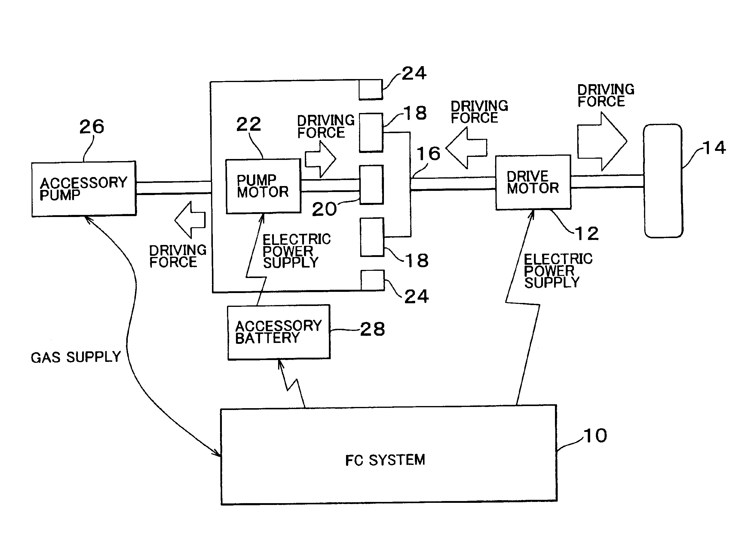
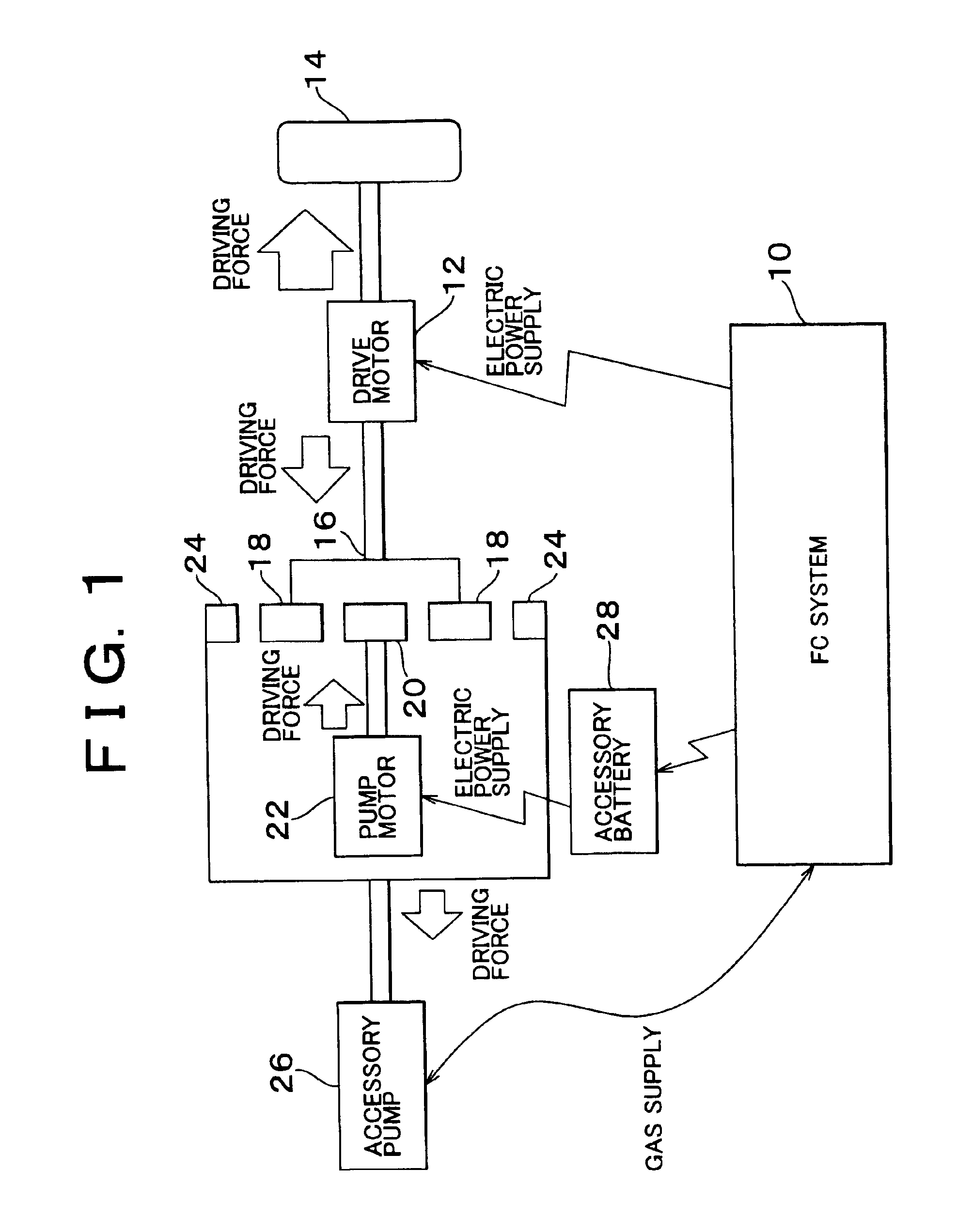
[0022]FIG. 1 illustrates a principal part of a fuel-cell vehicle equipped with an accessory drive apparatus according to the preferred embodiment of the invention. A fuel cell system (FC) 10 installed on the vehicle is operable to supply electric power required for running the vehicle to a drive motor 12. An output shaft of the drive motor 12 is connected to vehicle wheels 14, and is also connected to a carrier 16 of a planetary gear unit. With this arrangement, driving force or power generated by the drive motor 12 is transmitted to the wheels 14, and is also transmitted to the planetary gear unit.

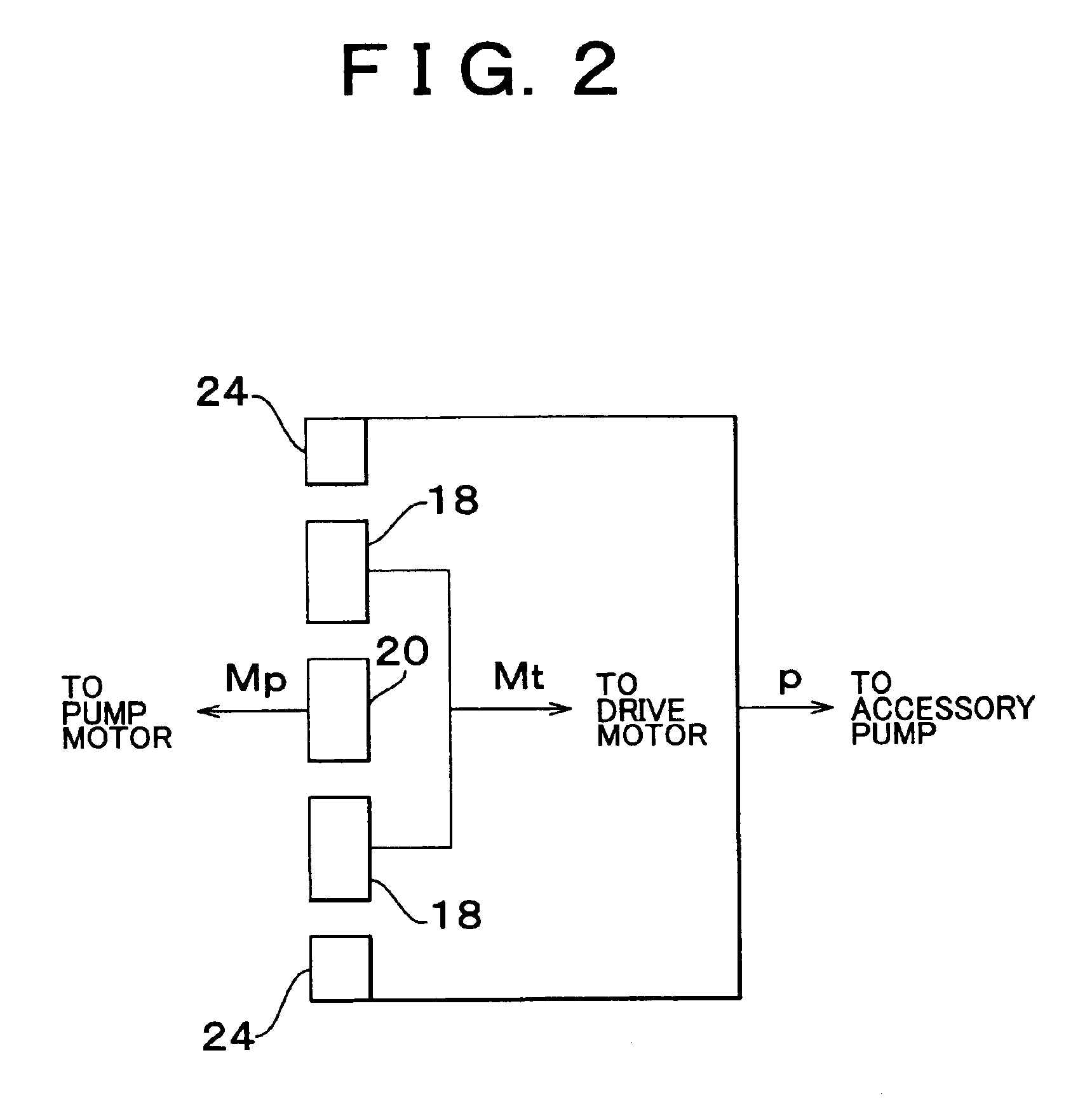
[0023]The planetary gear unit includes the carrier 16, a pinion gear 18 provided on the carrier 16, a sun gear 20, and a ring gear 24. The sun gear 20 and the pinion gear 18, and the ring gear 24 and the pinion gear 18, respecti...


PUM


Abstract

An accessory drive apparatus includes a power source, an accessory system that provides an input to the power source, an accessory driving source that drives the accessory system, and a power combination / distribution mechanism that is connected to the power source and the accessory system to transmit power from both the power source and the accessory driving source to the accessory system. With this arrangement, the accessory system is driven by a combination of power received from the accessory driving source and the power source.

Description

INCORPORATION BY REFERENCE[0001]The disclosure of Japanese Patent Application No. 2001-046376 filed on Feb. 22, 2001, including the specification, drawings and abstract, is incorporated herein by reference in its entirety.BACKGROUND OF THE INVENTION[0002]1. Field of the Invention[0003]The invention relates to an accessory drive apparatus, and more particularly to a driving mechanism for an accessory system for driving a power source, such as a fuel cell system.[0004]2. Description of Related Art[0005]Japanese Laid-open Patent Publication No. 6-229447 discloses a transmission device for transmitting rotary power of an engine to an engine accessory while changing the speed of rotation, so as to drive the engine accessory. The transmission device disclosed in this publication includes a hollow rotating member, a first gear, a second gear, and a clutch. The hollow rotating member, which is rotatably supported on a drive shaft of the accessory, has an input engaging portion formed at an ...

Claims


Application Information

Patent Timeline
Patent Type & Authority Patents(United States)
IPC IPC(8): F02B63/04F02B63/00B60K1/04B60L1/00B60L11/18F02B67/04F16H1/28
CPCF02B63/04
Inventor ISHIKAWA, TETSUHIROSASAKI, SHOICHISHAMOTO, SUMIKAZUSUGIURA, HIROSHIINAGUMA, YUKIOMORIYA, KAZUNARI
Owner TOYOTA JIDOSHA KK
Learn More