
Air drop device

a drop device and air technology, applied in parachutes, parachutes without canopies, emergency apparatus, etc., can solve the problems of not being able to reliably or accurately position the parachutes, the drop cannot be easily retrieved, and the drop cannot be retrieved. to the wrong hands, so as to reduce the length of the tether

Inactive Publication Date: 2005-09-13
MORRIS DAVID C
View PDF12 Cites 21 Cited by
  • Summary
  • Abstract
  • Description
  • Claims
  • Application Information

AI Technical Summary

Benefits of technology

[0003]The present invention is an air drop device that includes a frame defining a through-hole and that supports a substantially vertical axle, substantially central to the through-hole. A blade assembly is rotatably mounted to the substantially vertical axle. Also, at least three tethers are connected to the frame and are adapted to be connected to the load. In addition, a set of tether length adjust devices, each located on a different one of said tethers, are capable to take-up some of the tether to reduce the length of said tether.

Problems solved by technology

The current and predominant means of delivering small unit bundles—parachute and / or impact resistant packing—for either logistics or humanitarian relief, provide no way to direct the bundles to a target in a controlled manner to insure safe delivery.
In areas of strong, high altitude wind and wind shear, such as in the mountains of Afghanistan, parachutes cannot be positioned either reliably or accurately: drops can drift into the wrong hands.

Method used


Image

  • Air drop device
  • Air drop device
  • Air drop device

Examples


Embodiment Construction

)

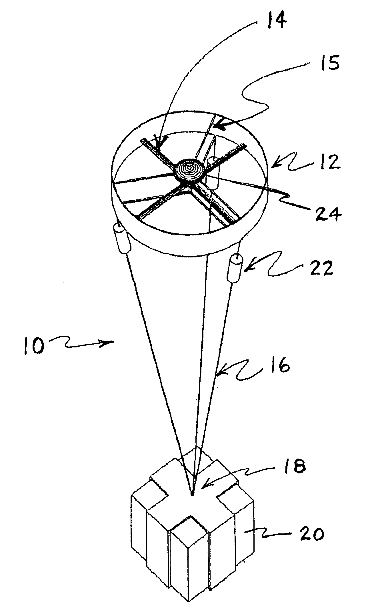
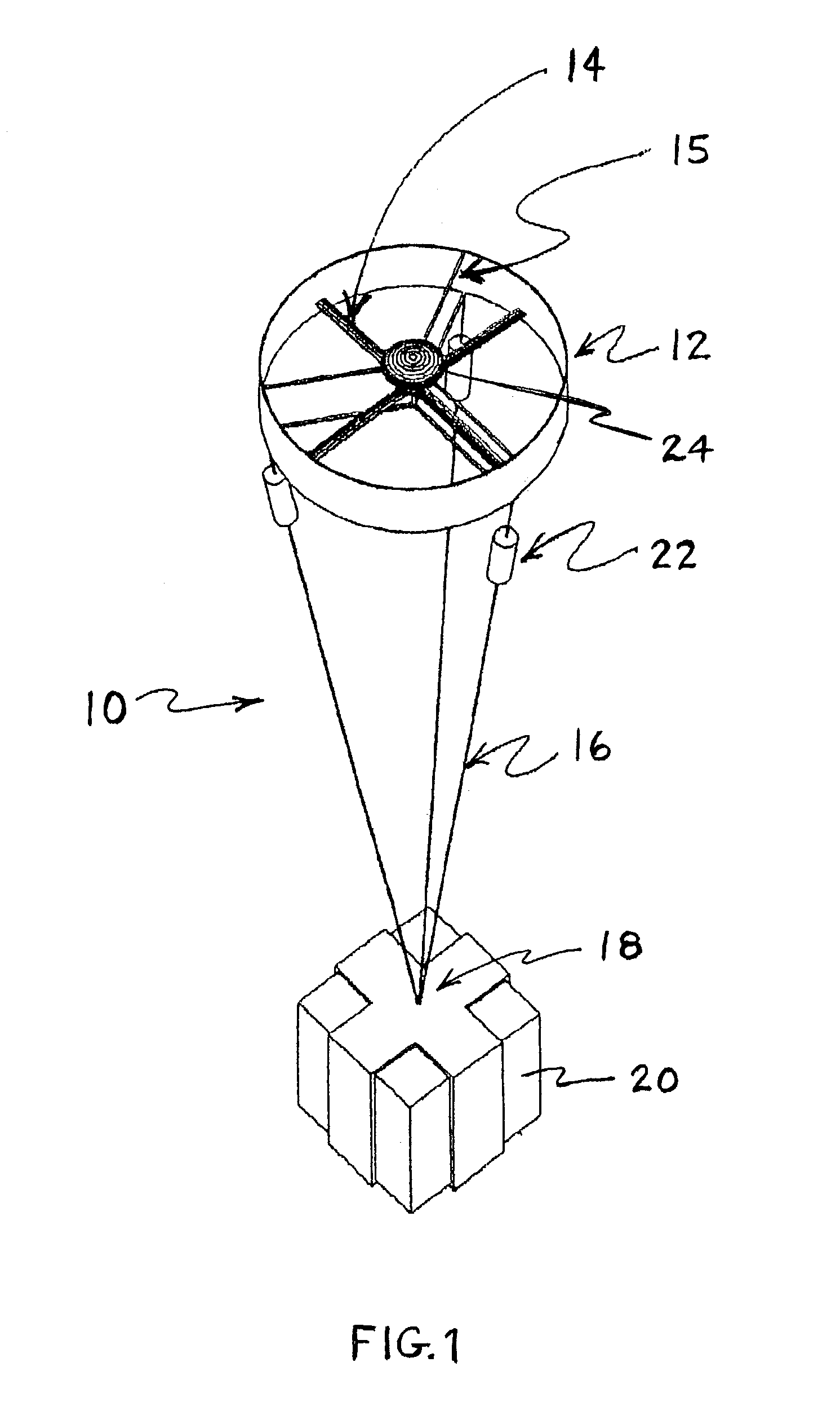
[0012]An air drop device 10 includes a frame 12 in the form of a short duct. Helicopter-like blades 14 are rotatably mounted to an axle (not shown) supported by a set of fin stabilizers 15 of frame 12. The pitch of the blades 14 is collectively controllable. Attached to the bottom of the frame are three tethers 16, which converge to a point 18: the attachment point for a parcel 20.

[0013]The free-drop device 10 is released into the air from a sufficiently high altitude, and the blades spin up due to autorotation. At a critical speed the pitch of the blades is increased and the rate of descent of the device slows: near the ground the rate is ideally slowed to zero for a soft landing.

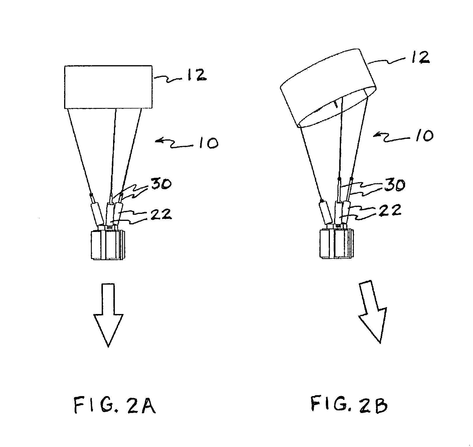
[0014]Each tether 16 has a tether length adjust device 22 that allows for effective contraction or elongation of the tether 16: as these devices 22 are selectively contracted or elongated the orientation of the frame 12 with respect to the parcel changes: this allows the device to be directed to its desti...


PUM


Abstract

An air drop device that includes a frame defining a through-hole and that supports a substantially vertical axle, substantially central to the through-hole. A blade assembly is rotatably mounted to the substantially vertical axle. Also, at least three tethers are connected to the frame and are adapted to be connected to the load. In addition, a set of tether length adjust devices, each located on a different one of said tethers, are capable to take-up some of the tether to reduce the length of said tether.

Description

RELATED APPLICATIONS[0001]This application claims priority from U.S. provisional patent application Ser. No. 60 / 388,706, filed on Jun. 13, 2002.BACKGROUND OF THE INVENTION[0002]The current and predominant means of delivering small unit bundles—parachute and / or impact resistant packing—for either logistics or humanitarian relief, provide no way to direct the bundles to a target in a controlled manner to insure safe delivery. In areas of strong, high altitude wind and wind shear, such as in the mountains of Afghanistan, parachutes cannot be positioned either reliably or accurately: drops can drift into the wrong hands.SUMMARY OF THE INVENTION[0003]The present invention is an air drop device that includes a frame defining a through-hole and that supports a substantially vertical axle, substantially central to the through-hole. A blade assembly is rotatably mounted to the substantially vertical axle. Also, at least three tethers are connected to the frame and are adapted to be connected...

Claims


Application Information

Patent Timeline
IPC IPC(8): B64D17/00B64D17/02B64D1/02B64D19/02
CPCB64D1/02B64D19/02
Inventor MORRIS, DAVID C.
Owner MORRIS DAVID C
Learn More