Training simulator for sharp shooting

a training simulator and simulator technology, applied in the field of training simulators, can solve the problems of only detecting the light-receiving element, no way of indicating the target hit, complex and expensive electronic training equipment, etc., and achieve the effect of expanding the scope of training

Inactive Publication Date: 2005-09-13
LVOVSKY MIKHAIL
View PDF11 Cites 25 Cited by
  • Summary
  • Abstract
  • Description
  • Claims
  • Application Information

AI Technical Summary

Benefits of technology

[0021]It is a further object of the present invention to provide a sharp shooting simulator allowing to practice taking out the weapon, its handling, aiming, and pulling the trigger with full realism corresponding to firing real live weapons.
[0022]It is yet a further object of the present invention to provide a simulator for sharp shooting allowing to further expand the scope of training beyond simple firing, such as for example finding the target in the realistically simulated surroundings.
[0024]The simulator of the invention is based on a number of functional units connected directly or remotely to the central computer for controlling the operation and recording the shooting results. The weapon unit is untethered and includes a real hand gun equipped with an emitter unit sending simultaneously two beams upon pulling the trigger—a wide angle infrared beam and a narrowly focused and aimed at the target light beam. The infrared beam is registered by the sensor near the screen and a signal indicating a firing event is sent to the computer. The light beam, preferably from a laser source is sent towards the screen, reflected therefrom towards the optical block and travels through a number of fixed and rotating mirrors and through a light divider to the light sensor. That sensor when activated sends the HIT or MISS signal to the computer. Importantly, the optical travel path of the reflected from the screen light beam coincides with the travel path of the light beam generating the target of the screen. Controlled by the computer, rotation of the rotating mirrors both places the target at a specific area of the screen as well as accepts the light beam from the screen to be registered by the light sensor. The target generator allows to position the target on the screen in any desirable area or to move it with constant or variable speed along a predetermined complex path on the screen. A video projector allows adding of the pre-recorded of virtual computer-generated surrounding scene onto the screen to increase the degree of realism of the shooting exercise.

Problems solved by technology

There is no way of indicating, however, that the target has been hit other than by stopping the movement of the projected image.
When used alone, however, such a light-receiving element can only detect whether or not a light beam discharged by a light gun has landed within a specified range on a target defined by the area of the light-receiving surface.
Voluminous light-receiving elements have been used resulting in complex and expensive electronic training equipment.
To its detriment, and to the detriment of the user of such a device, lead sighting, which is required in actual clay shooting, cannot be simulated by this system.
Many firing ranges have limited capacity.
Moreover, most existing firing ranges do not provide protection for the shooter against the natural elements such as rain or snow.
Because of the noise levels normally associated with firing ranges, they are typically located in remote areas requiring people to have to drive to such remote locations.
The ammunition, targets and use costs for the range make such adventures expensive.
Furthermore, when live ammunition is used, expense, risks, administrative problems, safety concerns, and government rules and regulations are more burdensome.
Another limitation of these systems is the need for a large number of training films associated with various situations encountered by various types of trainees.
Yet another limitation is in the repetitive nature of the typical firing situations presented to the trainees.
There is no easy way to reprogram the firing aim position, movement direction, or speed depending on the specific needs of a particular category of shooters.
These and other prior art weapon simulators, training devices, equipment, techniques, and methods have met with varying degrees of success, but are often unduly expensive, difficult to use, complex and inaccurate.
None of these devices include a system that accurately simulates live ammunition shooting.
It is their common limitation that they have a very small number of training situations available, especially those with increasing difficulty of firing conditions.

Method used


Image

  • Training simulator for sharp shooting
  • Training simulator for sharp shooting
  • Training simulator for sharp shooting

Examples


Embodiment Construction

[0029]A detailed description of the present invention follows with reference to accompanying drawings in which like elements are indicated by like reference letters and numerals.

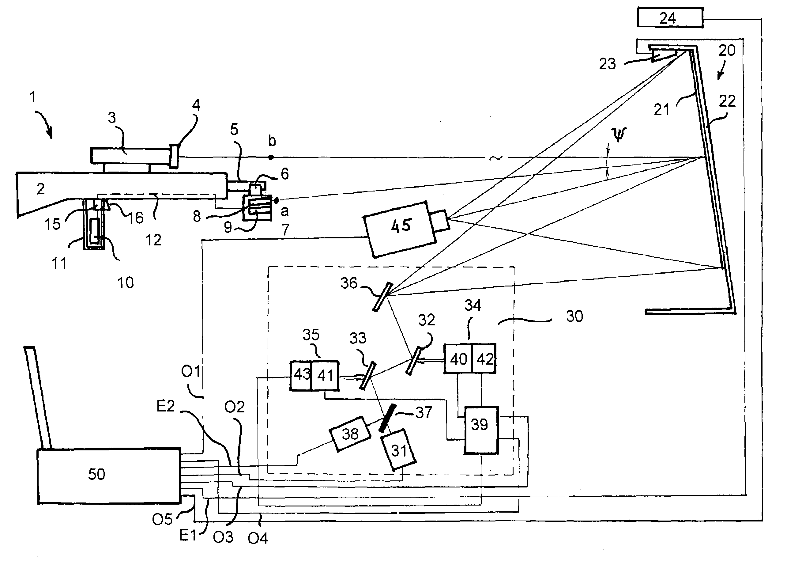
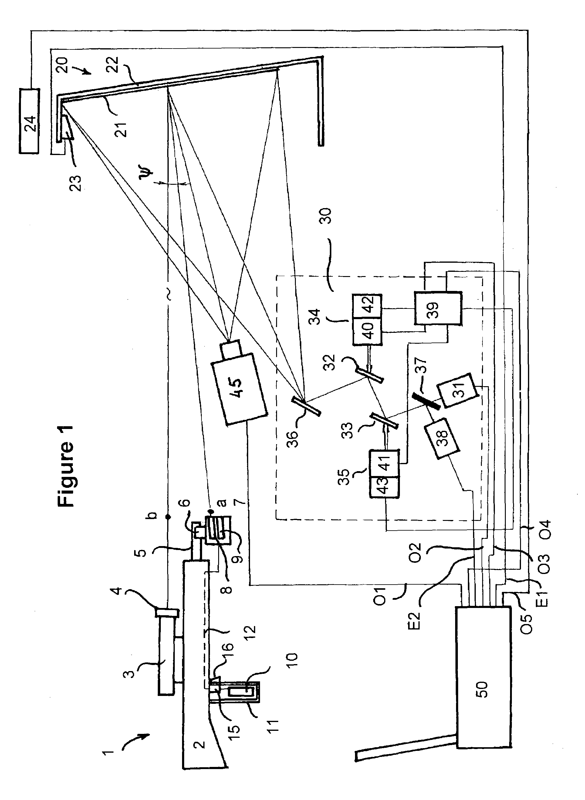
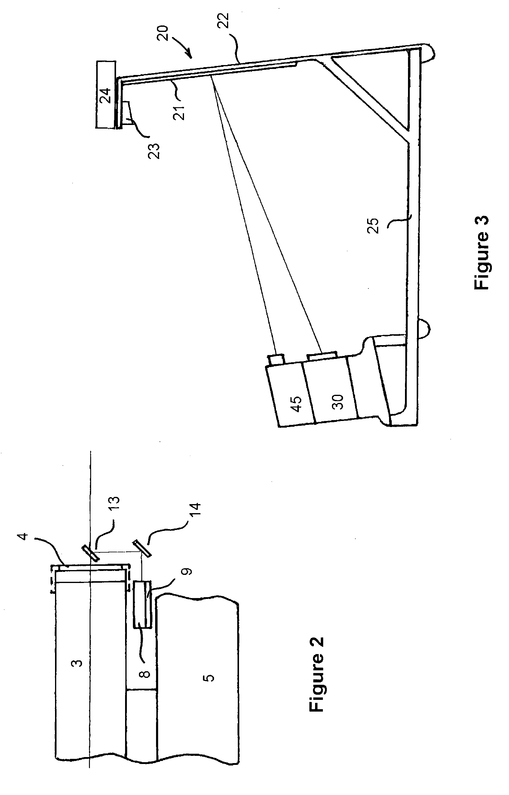
[0030]FIGS. 1 and 3 illustrate the general diagram and the relative positioning of the various units of the proposed simulator. The simulator consists of the weapon unit 1 as well as a screen unit 20, optical unit 30, video projector unit 45, all mounted on the base frame 25. In addition, a computer unit 50 is designed to control all functional aspects of the simulator. The following is a more detailed description of various units of the device.

[0031]The weapon unit 1 includes a weapon 2, which is used as a mounting base for all the other elements of the weapon unit 1. All commonly known standard personal firing weapons such as shotguns, rifles, pistols, and handguns can be used as the weapon unit 2. An optical aiming device 3 and a telescopic viewfinder 4 are mounted on the upper part of the weapon 2. The v...


PUM


Abstract

The simulator of the invention is based on a number of functional units connected directly or remotely to the central computer for controlling the operation and recording the shooting results. The weapon unit is untethered and includes a real hand gun equipped with a snap-on emitter unit to send simultaneously two beams of light upon pulling the trigger—a wide angle infrared beam and a narrowly focused and aimed at the target light beam. The infrared beam is registered by the sensor near the screen and a signal indicating a firing event is sent to the computer. The light beam, preferably from a laser source is sent towards the screen, reflected therefrom towards the optical block and travels through a number of fixed and rotating mirrors and through a light divider to the light sensor. That sensor when activated sends the HIT or MISS signal to the computer. Importantly, the optical travel path of the reflected from the screen light beam coincides with the travel path of the light beam generating the target of the screen. Controlled by the computer, rotation of the rotating mirrors both places the target at a specific area of the screen as well as allows accepting of the light beam from the screen by the light sensor. The target generator allows to position the target on the screen in any desirable area or to move it with constant or variable speed along a predetermined complex path on the screen. A video projector allows adding of the pre-recorded of virtual computer-generated surrounding scene onto the screen to increase the degree of realism of the shooting exercise.

Description

BACKGROUND OF THE INVENTION[0001]The present invention relates generally to training simulators for improving the marksmanship and firing tactics for combat troops, police, sportsmen's clubs, and other similar groups. In particular, the simulator of the invention relates to devices providing increasing levels of firing difficulty as well as increasing number of moving targets while automatically keeping the score of hits and misses as well as the number of shots fired.[0002]It has long been desired to provide personnel training to improve their skills in aiming and firing shotguns, rifles, handguns, and other weapons. In the past, many different types of target practice and aiming devices have been suggested that use light to simulate the firing of a gun. Such devices help train and instruct shooters by enabling them to practice aiming at a target either indoors or on an open range without actually making use of real projectiles (e.g. shot charges or bullets) The position of a proje...

Claims


Application Information

Patent Timeline
Patent Type & Authority Patents(United States)
IPC IPC(8): F41A33/00F41G3/26F41G3/00G09B19/00F41A33/02G06F
CPCF41A33/02
Inventor LVOVSKIY, MATVEY
Owner LVOVSKY MIKHAIL
Why Eureka
Try Eureka