Spinal fusion interbody spacer

Active Publication Date: 2005-09-13
WARSAW ORTHOPEDIC INC
View PDF34 Cites 206 Cited by
  • Summary
  • Abstract
  • Description
  • Claims
  • Application Information

AI Technical Summary

Benefits of technology

[0016]Therefore, the objects of the present invention include: providing an interbody spacer or fusion cage device having convex upper and lower bearing or abutment surfaces for implanting between a pair of adjacent vertebrae to properly space the vertebrae and/or to promote fusion between the vertebrae; providing such a device in which the peak of convexity of the abutment surfaces is positioned somewhat anterior of a medial plane midway between anterior and posterior surfaces of the spacer; providing such a device in which the convex abutment surfaces are formed by planar facets, including at least a peak facet, an anterior inclined facet, and a posterior inclined facet, all cooperating as a single unit or unitary piece so as to produce a functional curve; providing such a device formed of a material which is appropriate to the long term disposition of the device desired, such as a biologically inactive metallic material, a biologically inactive non-metallic material, a biologically active bone-based material, or a biologically active non-bone-based material; providing such a device having cylindrically concave lateral or side surfaces that join the upper and lower abutment surfaces on opposite lateral sides of the device; providing such a device having a plurality of side channels opening onto each concave lateral side surface and being laterally outward open along the entire length thereof between inferior and superior surfaces of the device; providing such a device wherein the structure of the interbody spacer device is strong, while minimizing volume and weight; providing a device having a solid central core or body; providing such a device which enables relatively close

Problems solved by technology

The vertebrae may also become compressed or otherwise damaged.
Vertebrae often become too closely spaced anteriorly due especially to age, but also because of other factors that often produce an undesired abnormal curvature of the spine with respect to lordosis o

Method used


Image

  • Spinal fusion interbody spacer
  • Spinal fusion interbody spacer
  • Spinal fusion interbody spacer

Examples


Embodiment Construction

[0031]As required, detailed embodiments of the present invention are disclosed herein; however, it is to be understood that the disclosed embodiments are merely exemplary of the invention, which may be embodied in various forms. Therefore, specific structural and functional details disclosed herein are not to be interpreted as limiting, but merely as a basis for the claims and as a representative basis for teaching one skilled in the art to variously employ the present invention in virtually any appropriately detailed structure.

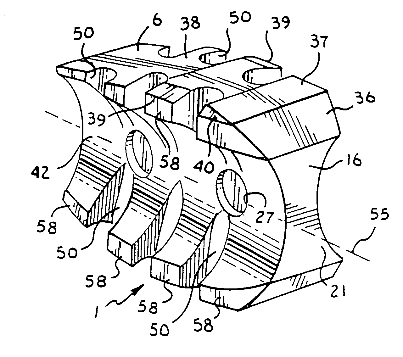
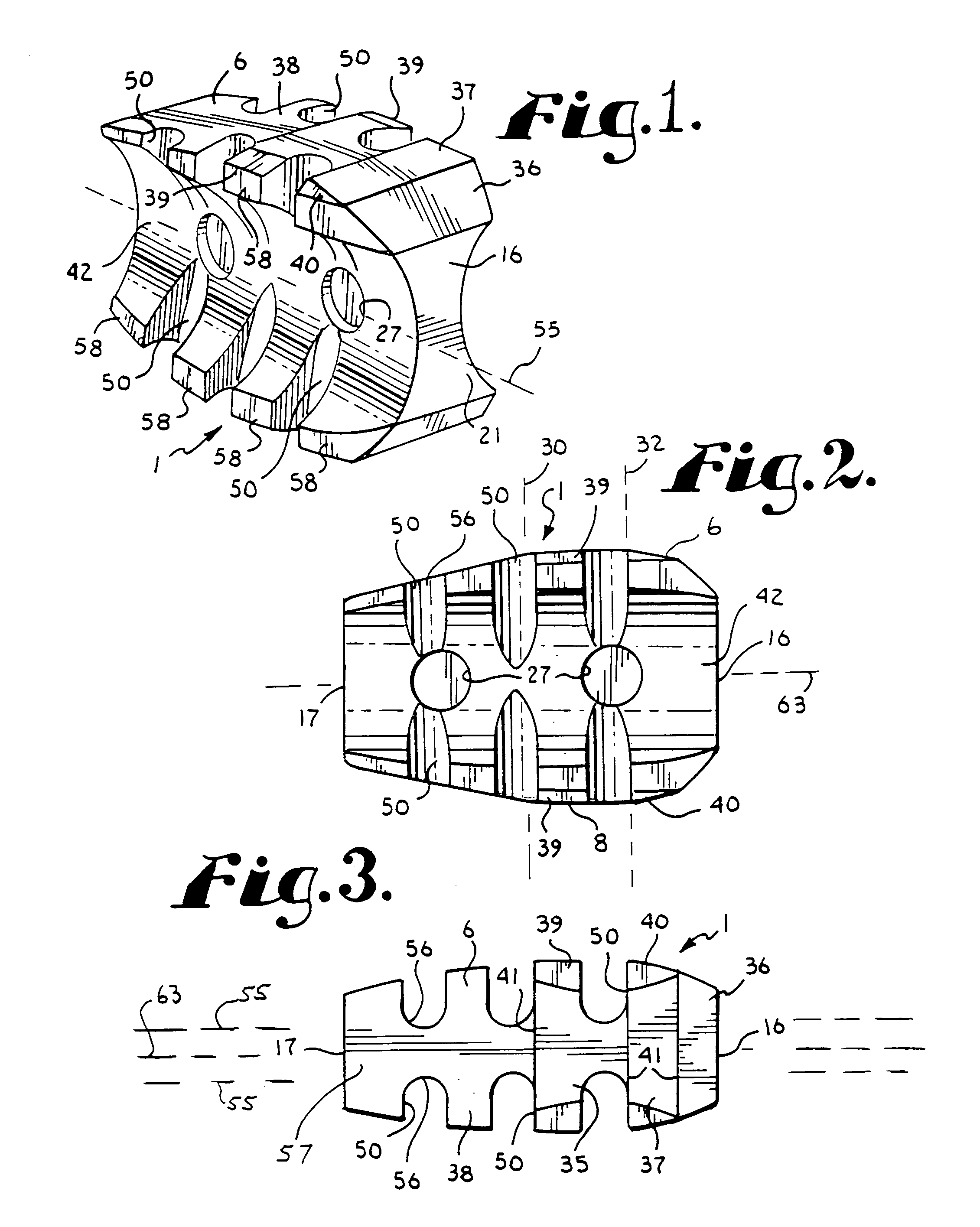
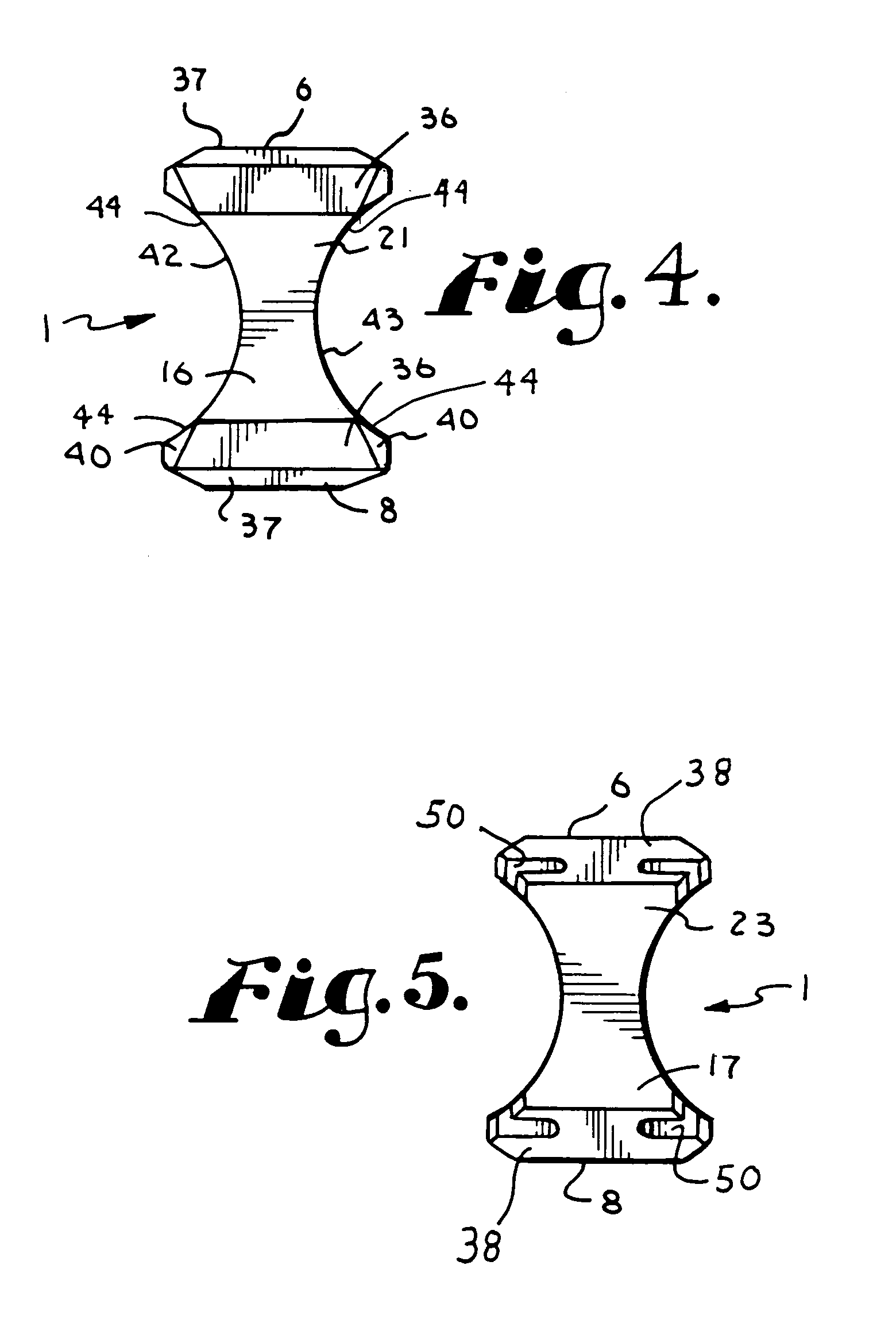
[0032]The reference numeral 1 generally designates a convex spinal fusion interbody spacer device which embodies the present invention. The device 1 is used to maintain proper spacing between a pair of adjacent vertebrae 3 and 4 of a human spine as a replacement for the intervertebral disc and to promote fusion between the vertebrae 3 and 4, preferably in conjunction with other implants, as noted below. In particular, the device 1 has a superior (or upper) su...


PUM


Abstract

A convex spinal fusion interbody space device includes spaced apart superior and inferior abutment surfaces which are effectively medially convex. The peak of such convexity is displaced anteriorly of a central plane through the device. The spacer device has front to rear lateral concave surfaces and top to bottom lateral side channels that intersect with said convex surfaces. The spacer device has a height which is greater than the width of the device. The spacer device is implanted between a pair of adjacent vertebrae by insertion in a tipped-over orientation and then reoriented to an upright orientation for engagement by facing surfaces of the vertebrae. Fusion promoting bone material is packed between the vertebrae and about the spacer device subsequent to implantation.

Description

BACKGROUND OF THE INVENTION[0001]The present application is directed to an interbody device for implantation between a pair of adjacent vertebrae in order to provide support to the vertebrae and / or promote bone fusion between the vertebrae and, in particular, to an interbody device having opposed concave sides with a plurality of laterally opening side channels and a front to rear convex or trapezoidal side view for the upper and lower surfaces.[0002]In the human spine the pad or disc between vertebrae is sometimes damaged or deteriorates due to age, disease, injury, or congenital defect. The vertebrae may also become compressed or otherwise damaged. Vertebrae often become too closely spaced anteriorly due especially to age, but also because of other factors that often produce an undesired abnormal curvature of the spine with respect to lordosis or kyphosis. Because of this, surgery is often utilized to place spacers or interbody devices between the vertebrae which provide proper sp...

Claims


Application Information

Patent Timeline
IPC IPC(8): A61B17/56A61F2/44A61B17/02A61F2/00A61F2/30A61F2/46
CPCA61F2/4455A61F2/4611A61B2017/0256A61F2002/3013A61F2002/30313A61F2002/30601A61F2002/30795A61F2002/30818A61F2002/3082A61F2002/448A61F2002/4627A61F2002/4628A61F2230/001A61F2230/0063
Inventor JACKSON, ROGER P.
Owner WARSAW ORTHOPEDIC INC
Why Eureka
Try Eureka