Pressure exhaust system for a convection cooking appliance

a technology of pressure exhaust system and convection cooking appliance, which is applied in the field of pressure exhaust system for convection cooking appliance, can solve the problems of large smoke cloud that could pour out, large ducting, and inability to cool down, and achieve the effect of sufficient tim

Inactive Publication Date: 2005-09-13
MAYTAG
View PDF9 Cites 27 Cited by
  • Summary
  • Abstract
  • Description
  • Claims
  • Application Information

AI Technical Summary

Benefits of technology

[0008]The present invention is directed to a cooking appliance incorporating a convection heating system including a ventilation arrangement having a pressure exhaust system. Specifically, the convection system includes a housing unit having an interior portion within which is arranged at least a fan assembly, a heating element and an exhaust outlet portion. The exhaust outlet portion has arranged therein a plurality of controlled, vented openings, the number and size of which control a flow rate and volume of exhaust gases exiting the appliance.
[0009]In accordance with a preferred form of the invention, the heating element, preferably a sheathed, electric resistive element in the form of a halo, is positioned outside a perimeter of the fan assembly such that an airflow generated by the fan passes over the heating element. With this arrangement, a high pressure area is established just outside the fan perimeter and around the heating element. In a preferred arrangement, the exhaust outlet portion is positioned within the high pressure area such that a portion of the airflow is forced out at a controlled rate through the vented openings.
[0010]Correspondingly, as the airflow passes through the exhaust outlet, a slight reduction in pressure occurs creating a low pressure zone within the convection system. This pressure reduction is most pronounced at an inner portion of the fan assembly. Therefore, oven gases passing from the system at an established rate cause fresh air to be drawn into the system at a corresponding rate. With this arrangement, oxygen (O2) is available in sufficient amounts to provide for substantially complete combustion of airborne byproducts. Accordingly, a reduction of smoke, condensation and built-up food effluents is realized within the cooking appliance. Furthermore, CO generated by the cooking process is maintained at minimum levels such that smoke and other emissions remain below industry standards. Moreover, by controlling the exhaust flow rate, gases carried through the exhaust ducts have sufficient time to cool prior to being released into the surrounding environment.
[0011]Additional objects, features and advantages of the present invention will become more readily apparent from the following detailed description of a preferred embodiment when taken in conjunction with the drawings wherein like reference numerals refer to corresponding parts in the several views.

Problems solved by technology

On the other hand, if the gases are evacuated too slowly, a large smoke cloud could pour forth into the kitchen after completion of a closed door cooking process and, in particular, a broil operation.
For example, permitting the exhaust gas temperature to be too low will undesirably develop condensation of the food effluents and steam as the exhaust gases exit the oven.
In general, such systems require extensive ducting, catalyst reactors, outlet baffles or the like.
While each is effective to a degree, all require the use of additional, expensive components or systems which add to the overall cost and complexity of the oven.

Method used


Image

  • Pressure exhaust system for a convection cooking appliance
  • Pressure exhaust system for a convection cooking appliance
  • Pressure exhaust system for a convection cooking appliance

Examples


Embodiment Construction

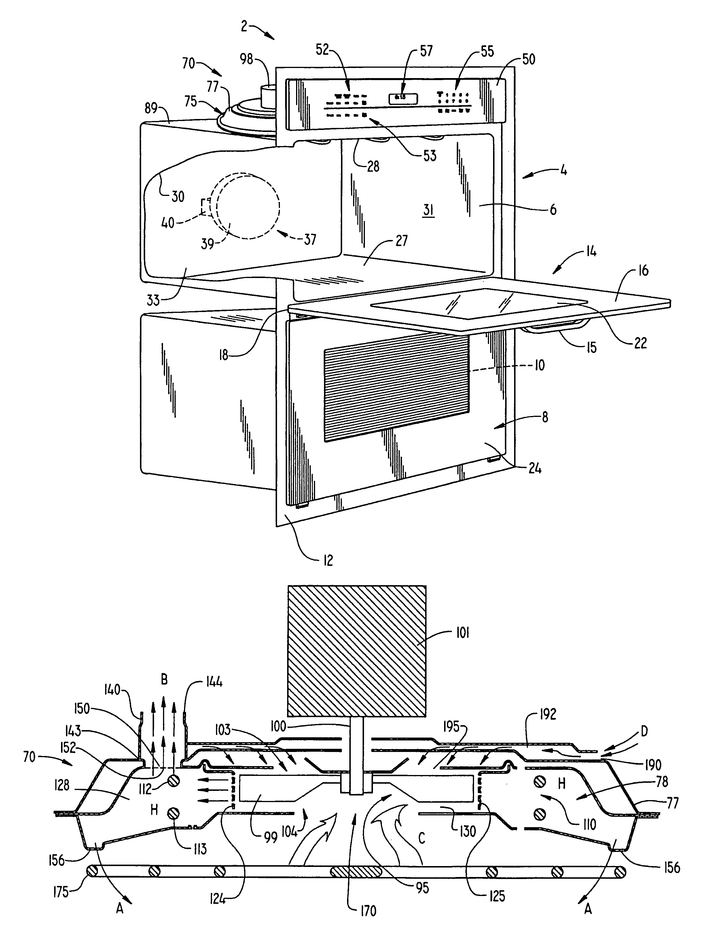
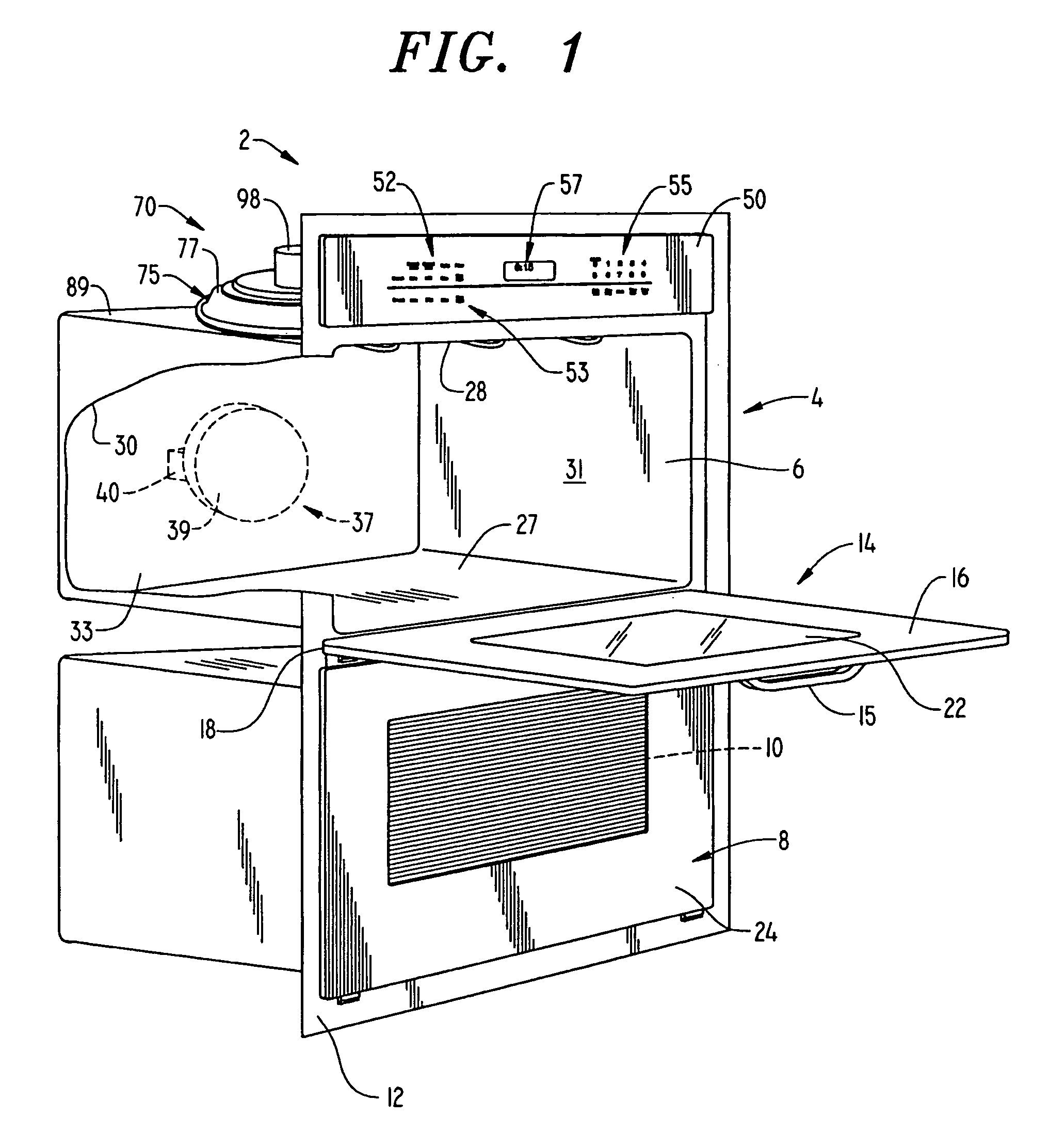
[0015]With initial reference to FIG. 1, a cooking appliance constructed in accordance with the present invention is generally illustrated at 2. Although cooking appliance 2 is depicted as a dual wall oven, it should be understood that the present invention is not limited to this particular model type and can be incorporated into various other types of oven configurations, e.g., cabinet mounted ovens, free-standing ranges and slide-in ranges. In the embodiment shown, cooking appliance 2 includes an upper oven 4 having upper oven cavity 6 and a lower oven 8 including a lower oven cavity 10. Upper oven 4 is preferably designed to perform a combination microwave / convection cooking process, while lower oven 8 is adapted to perform a conventional, radiant cooking operation. As shown, cooking appliance 2 includes an outer frame 12 for, at least partially, supporting both upper oven 4 and lower oven 8 within associated wall structure (not shown).

[0016]In a manner known in the art, a door as...


PUM


Abstract

A cooking appliance incorporates a convection heating system including a housing having an interior portion, a fan assembly, a heating element and an exhaust outlet duct. The exhaust outlet duct, within which is arranged a plurality of controlled vent openings, is positioned in a high pressure area of the convection heating system established about a periphery of the fan assembly and heating element. Oven gases are forced by the high pressure through the exhaust duct, thereby creating a corresponding reduction in pressure. The reduction in pressure establishes a low pressure area within the fan assembly which draws in fresh air in an amount equal to that exhausted through the exhaust duct.

Description

BACKGROUND OF THE INVENTION[0001]1. Field of the Invention[0002]The present invention pertains to the art of cooking appliances and, more particularly, to a cooking appliance including a convection cooking system having a controlled exhaust outlet that establishes a pressure differential within the convection cooking system causing fresh air to be drawn into the appliance.[0003]2. Discussion of the Prior Art[0004]In the art of cooking, it is common to incorporate a convection cooking system in an oven for performing a particular cooking process. Typically, convection cooking systems include a fan for establishing a heated airflow by passing oven gases over a heating element prior to re-introducing the airflow into the oven. In addition to the heated airflow, provisions must be made to exhaust a portion of the oven gases from the oven. Therefore, the convection cooking system must include structure designed to ventilate or evacuate exhaust gases from the appliance.[0005]There are two...

Claims


Application Information

Patent Timeline
Patent Type & Authority Patents(United States)
IPC IPC(8): A21B1/00A21B1/26F24C15/32F24C15/20
CPCF24C15/2007F24C15/325
Inventor WHIPPLE, JR., ROBERT Z.
Owner MAYTAG
Why Eureka
Try Eureka