Comb teeth type piezoelectric actuator and method for manufacturing the same

a piezoelectric actuator and comb teeth technology, applied in the direction of generators/motors, printing, solid-state devices, etc., can solve the problems of large misalignment, poor precision, and large misalignment between the piezoelectric layers of the comb teeth, and achieve excellent durability and reliability.

Inactive Publication Date: 2005-09-13
NGK INSULATORS LTD
View PDF16 Cites 10 Cited by
  • Summary
  • Abstract
  • Description
  • Claims
  • Application Information

AI Technical Summary

Benefits of technology

[0021]Further, since the slit portion is formed before firing and the interlayer between piezoelectric material layer—electrode material layer which is exposed to the outside in a finished product is a high-temperature fired surface, residual stress is relieved and interlayer separation does not substantially occur during processing or during use. Therefore, it is possible to obtain products with excellent durability and reliability. Also, a surface is hard to be contaminated and abnormalities due to contamination such as short-circuit defects etc. are not likely to occur during use.

Problems solved by technology

However, in an actuator which is formed by this method, as shown in FIG. 8 which shows an end surface looking from Q in FIG. 7, positions between piezoelectric layers of the comb teeth cannot be aligned with good precision, and big misalignment occurs.
Further, because of suppleness of the piezoelectric material green sheet, it was unavoidable that misalignment between the piezoelectric layers of approximate 20 μm in total occurs when 10 layers and more are laminated.
As a result, a characteristic of an actuator is dropped down, and further, stress concentration occurs at a boundary portion, and micro-cracks occur during use, which may be a case that it is grown to demolish an element.
Further, such a defect becomes a big problem in a refined comb teeth type actuator, such as a comb teeth pitch of 200 μm and below in particular.

Method used


Image

  • Comb teeth type piezoelectric actuator and method for manufacturing the same
  • Comb teeth type piezoelectric actuator and method for manufacturing the same
  • Comb teeth type piezoelectric actuator and method for manufacturing the same

Examples


Embodiment Construction

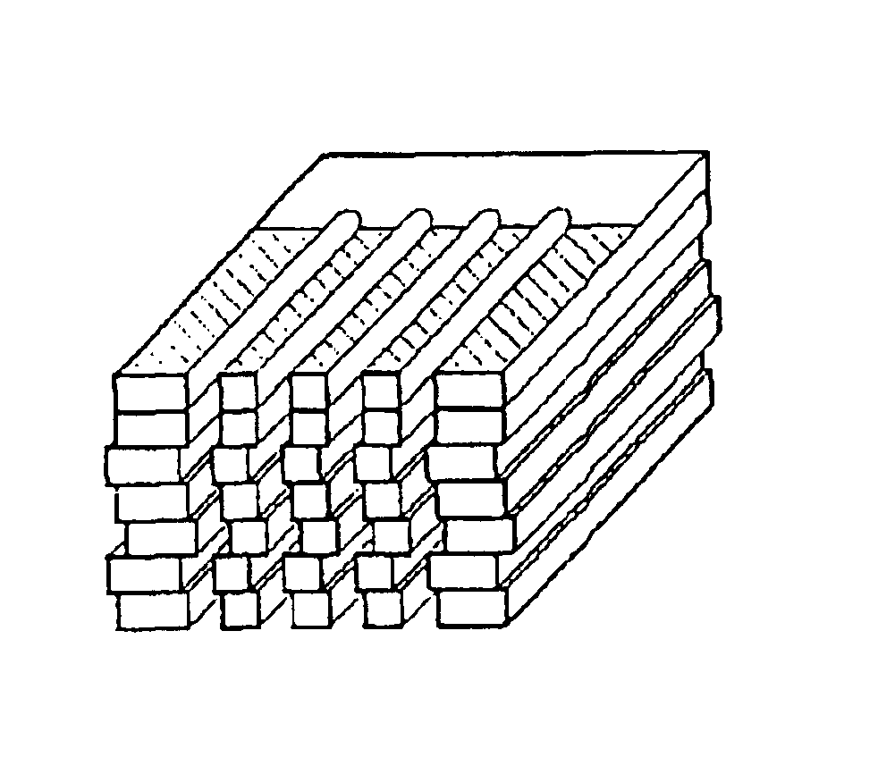
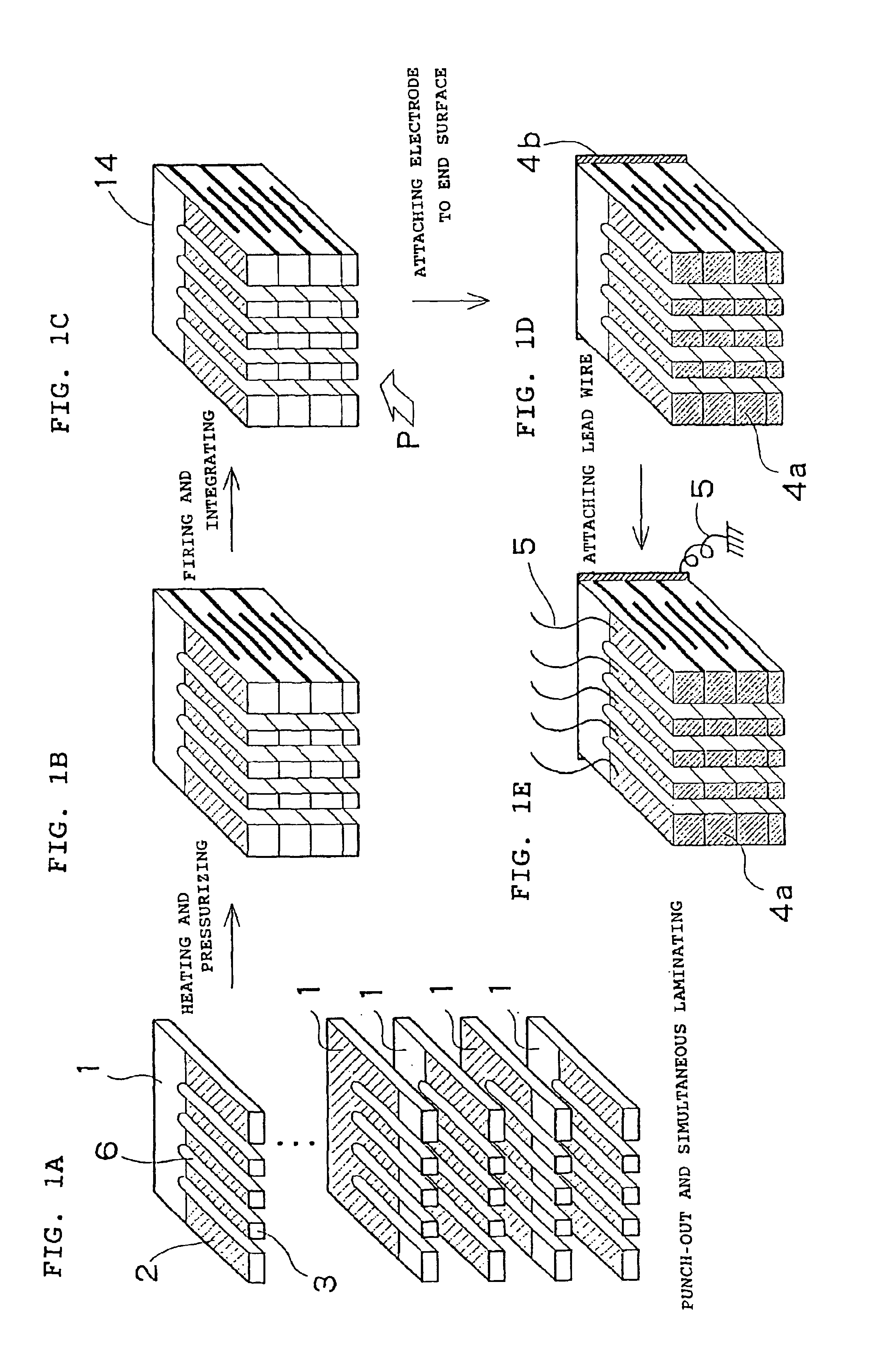
[0030]The invention will be described in detail with reference to the drawings. FIGS. 1A-D show one example of a comb teeth type piezoelectric actuator according to the invention, and an outline of a manufacturing process therefore. FIG. 1E shows a finished comb teeth type piezoelectric actuator. A manufacturing procedure is that, after forming an electrode film 2 on a piezoelectric material green sheet 1 (hereinafter, simply referred to as a sheet), slits 6 of each sheet 1 are formed as illustrated in FIG. 1A, i.e., the steps of forming comb teeth 3 and laminating the green sheets are carried out at the same moment by a method described later in which the comb teeth 3 are formed by laminating sheets, and by the time of completion of punching-out, the laminating of the layers is completed.

[0031]Then, respective layers are placed in contact, heated and pressurized as shown in FIG. 18, and fired as shown in FIG. 1C to obtain and a driving part 14 of a multi-layer piezo-actuator. There...


PUM

PropertyMeasurementUnit
distanceaaaaaaaaaa
distanceaaaaaaaaaa
widthaaaaaaaaaa

Abstract

A piezoelectric actuator includes comb teeth-shaped piezoelectric actuators, each comprising plural piezoelectric layers. A side surface of each tooth is fired. Actuators are made by (1) preparing a plurality of piezoelectric material green sheets on which electrode films are formed and forming slits on a first green sheet using a punch and a die, (2) pulling up the first green sheet using a stripper, (3) pulling up a top portion of the punch slightly from the lowest portion of the pulled up first green sheet, (4) forming second slits in a second green sheet by the punch, (5) pulling up the second green sheet jointly with the first green sheet, and (6) pulling up the top portion of the punch slightly from the lowest portion of the pulled up second green sheet, and thereafter laminating green sheets by repeating steps (4) through (6). The layers can thereafter be fired.

Description

CROSS REFERENCE TO RELATED APPLICATIONS[0001]This application is a continuation of International Application No. PCT / JP02 / 01911, having an international filing date of Mar. 1, 2002, which designated the United States, the entirety of which is incorporated herein by reference.[0002]This application also claims the benefit of Japanese Application 2001-057011, filed Mar. 1, 2001, the entirety of which is incorporated herein by reference.TECHNICAL FIELD[0003]This invention relates to a comb teeth type piezoelectric actuator and a method for manufacturing the same in which a plurality of driving parts, each comprising a plurality of piezoelectric layers, are aligned and allocated. In particular, this invention relates to a comb teeth type piezoelectric actuator and a method for manufacturing the same in which it is hard for interlayer separation to occur and it is also hard to be contaminated. Further, even in a case of comb teeth with a slit width of 70 μm and below and also in a case o...

Claims


Application Information

Patent Timeline
Patent Type & Authority Patents(United States)
IPC IPC(8): B41J2/14B41J2/16H01L41/083H01L41/22H01L41/339H01L41/39
CPCB41J2/14274B41J2/1612B41J2/1632B41J2/1637H01L41/083H01L41/273H01L27/20H01L41/339Y10T29/435Y10T29/42Y10T29/417Y10T29/49002Y10T29/49126H10N39/00H10N30/50H10N30/053H10N30/089
Inventor TAKEUCHI, YUKIHISATSUJI, HIROYUKIKITAMURA, KAZUMASATAKAHASHI, NOBUO
Owner NGK INSULATORS LTD
Why Eureka
Try Eureka