Mobile phone hand-free holder

a technology for hand-free holders and mobile phones, which is applied in the direction of electrical equipment, vehicle components, substation equipment, etc., can solve the problems of requiring a second set of tools, comparatively expensive to have one, and not so difficult to solve, so as to improve the structure of the hand-free holders

Inactive Publication Date: 2005-09-13
TSAY WEN FENG
View PDF2 Cites 70 Cited by
  • Summary
  • Abstract
  • Description
  • Claims
  • Application Information

AI Technical Summary

Benefits of technology

[0005]The primary purpose of the present invention is to provide an improved structure of a hand free holder for a mobile phone that can be adapted to a mobile phone with its plug socket not provided at the center of its base. To achieve the purpose, the holder is respectively connected to both ends of a cross link pivoted to the center of the holder; an insertion is provided to the end of the pivot of the cross link to slide in a lateral slide way in the upper casing; a coil spring is each provided to both sides of the slide way. The holder comprised of two identical halves has a serration provided on the edge of one side of each half. A resilient locking seat in U-shape is provided by the serration and has two stoppers protruding into the serration to cause the holder to only press inwardly and to be secured in position. Consequently, while pressing to hold the mobile phone in place, the holder is capable of pursuing the insertion provided to the pivot of the cross link to laterally displace along the slide way for the press center to deflect for securing a mobile phone having its plug socket not provided at the center in position.

Problems solved by technology

It was useful for a particular model of mobile phone and was comparatively expensive to have one.
This problem is not so difficult to be solved.
Accordingly, another set of tooling must be developed to suffer disadvantages of higher production cost, limited range of application, increased inventory of parts and storage capacity.
Besides, the plugging in and out of an earphone would compromise drive safety.

Method used


Image

  • Mobile phone hand-free holder
  • Mobile phone hand-free holder
  • Mobile phone hand-free holder

Examples


Embodiment Construction

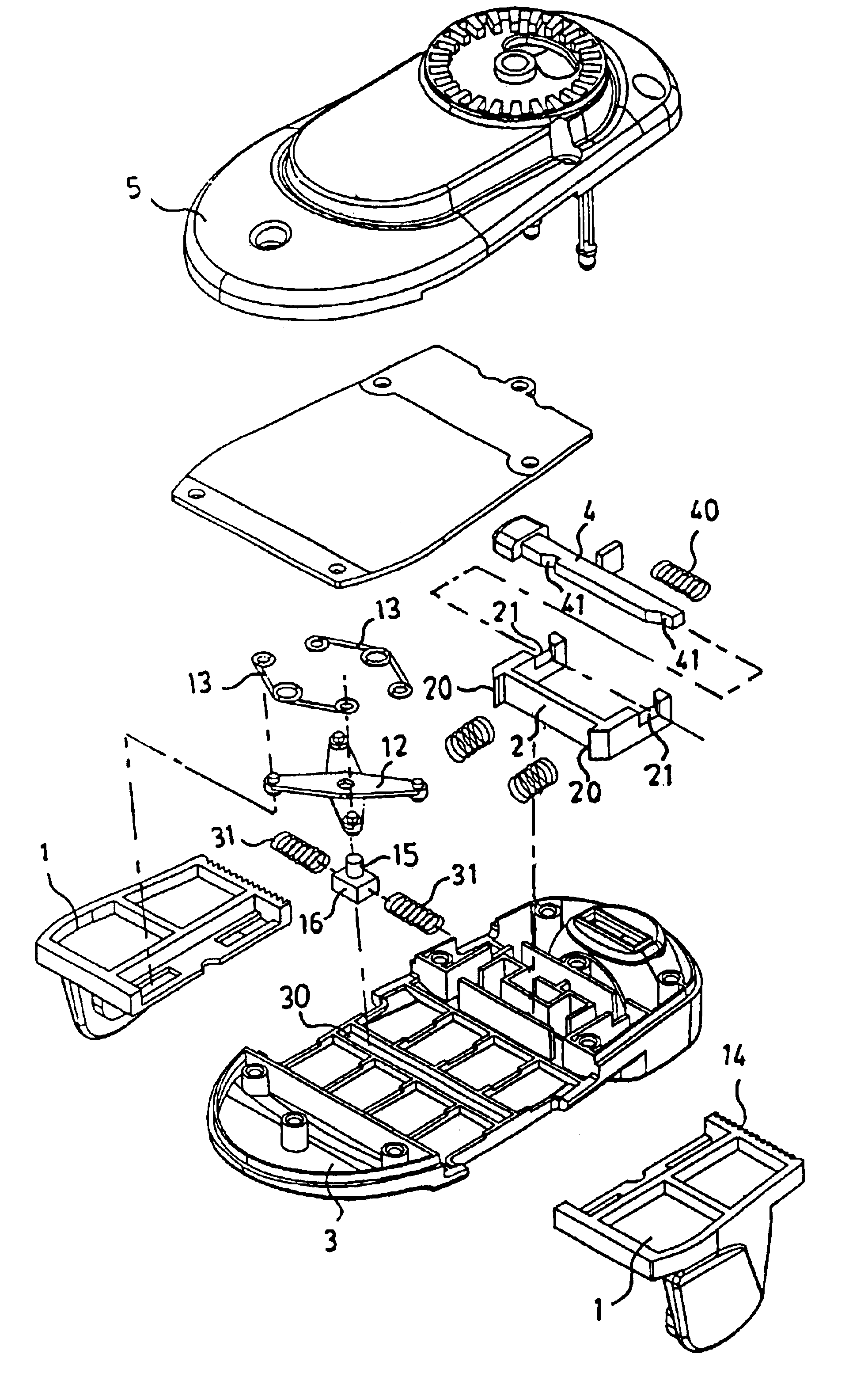
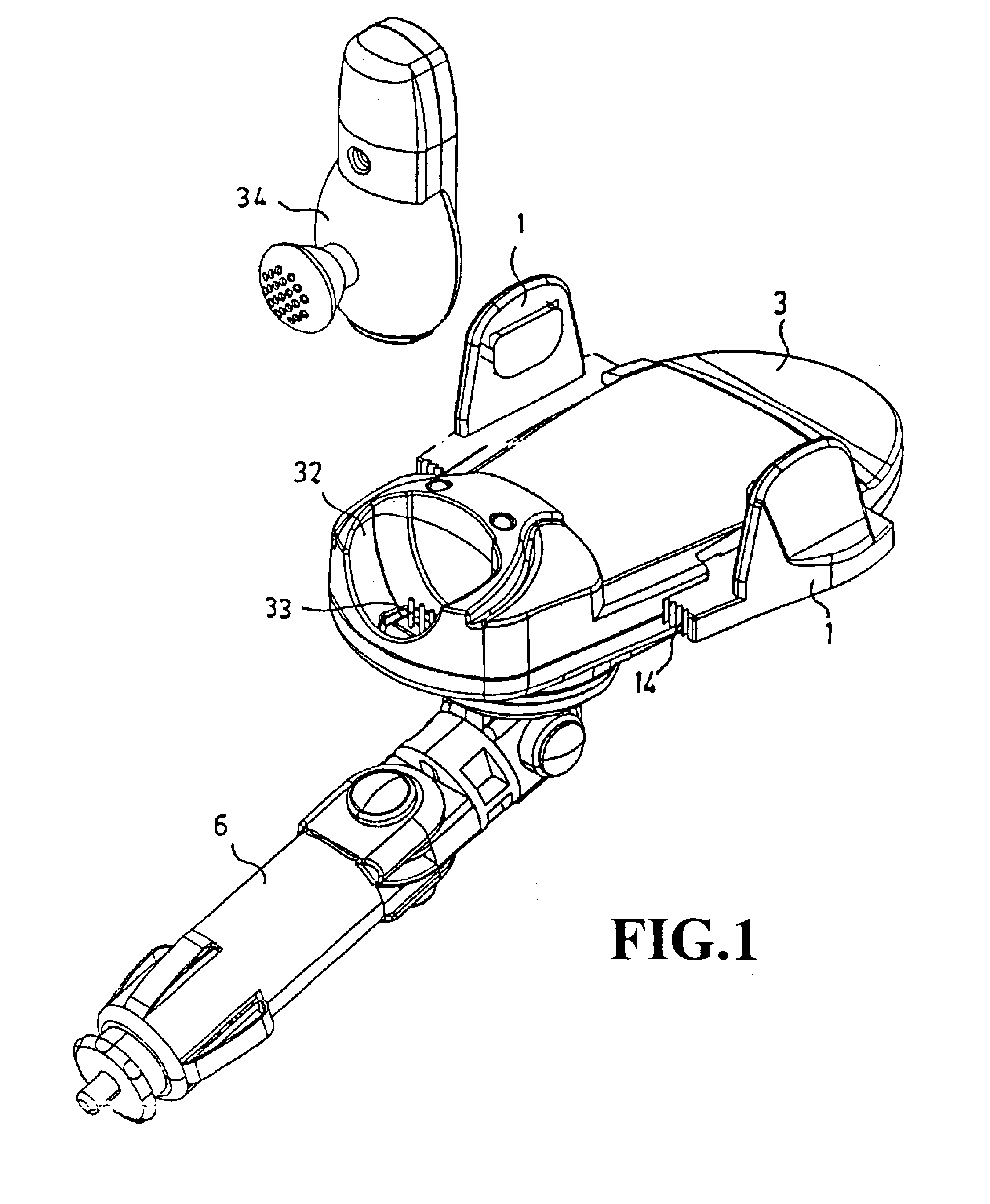
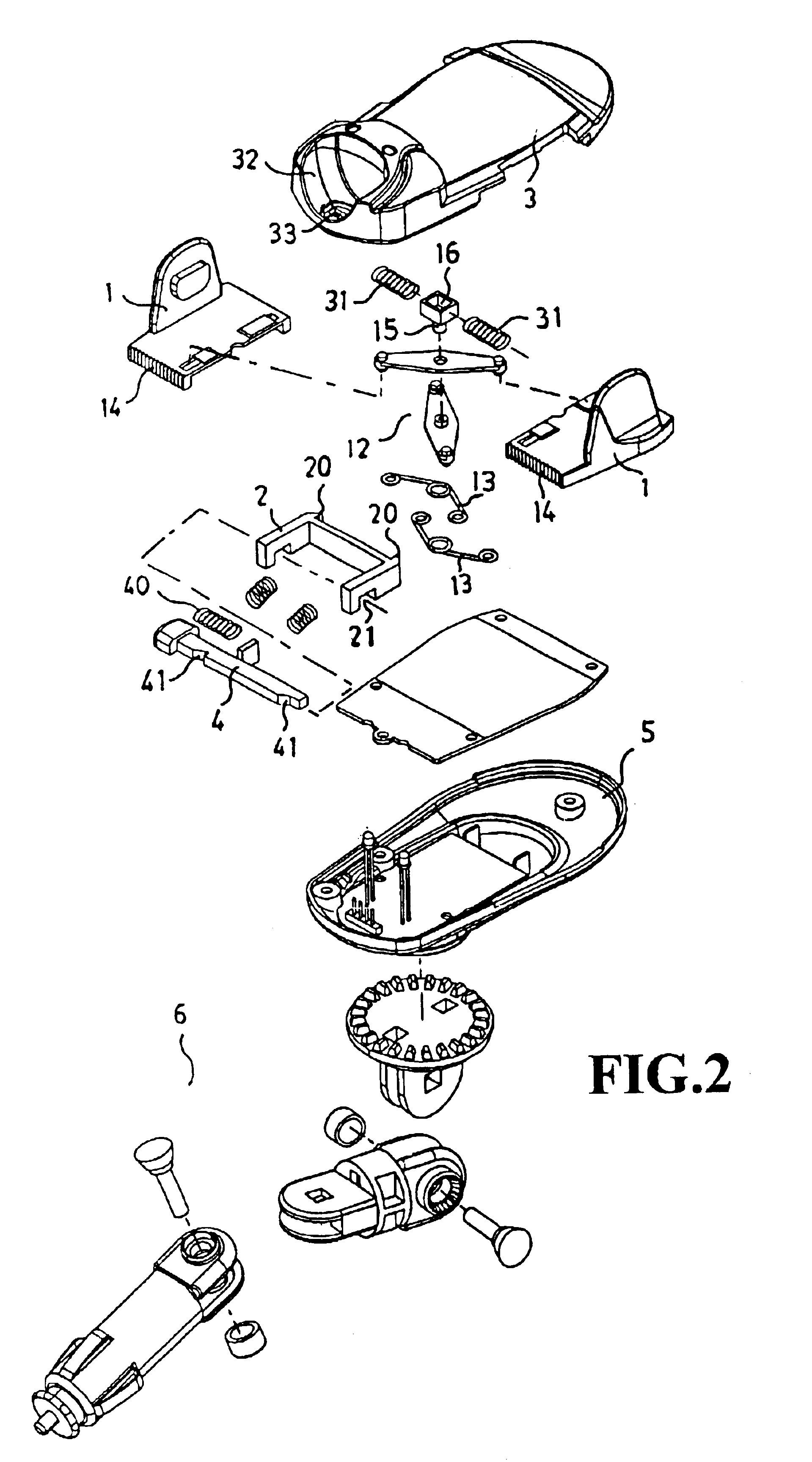
[0013]Referring to the accompanying drawings, a preferred embodiment of the present invention is essentially comprised of a holder (1), a resilient locking seat (2), a press lever (4), an upper casing (3) and a lower casing (5) in a structure is substantially similar to that disclosed in U.S. Pat. No. 5,903,645. Wherein, the holder (1) includes two identifiable halves, a right one and a left one arranged in symmetry to be inserted into where between the lower casing (5) and the upper casing (3), and respectively connected to both ends of a cross link pivoted at the center. As illustrated in FIG. 3, an insertion (16) attached to the lower end of the pivot (15) of the cross link (12) slides onto a lateral slide way (30) in the upper casing (3). A coil spring (31) is each provided on both sides of the lateral slide way (30) and a compression spring (13) is each provided on both sides between two halves of the holder (1) or two abutted ends of the cross link (12). One side of each half ...


PUM


Abstract

An improved structure of a mobile phone hand-free holder, includes a holder, an upper casing, a lower casing, a resilient locking seat and a press lever; a cross link pivoted to the center; an insertion protruding from end of the pivot to slide in a lateral slide way in the upper casing, both ends of the cross link being connected respectively to both sides of the holder; one side of the holder is serrated at the edge; the locking seat being provided by the serration to have two stoppers protruding into the serration to force the holder to only press inwardly to be held in position; an earphone socket also functioning as a switch to control transmission of an incoming call to be received by a cordless earphone or an external speaker or a car radio; the lateral displacement of the cross link in the slide way to deflect the center to hold a mobile phone with its plug socket not provided at the center.

Description

BACKGROUND OF THE INVENTION[0001](a) Field of the Invention[0002]The present invention is related to a mobile phone hand-free holder, and more particularly to an improved structure of a hand-free holder for a mobile phone, a U.S. Pat. No. 5,903,645 granted to this same inventor that can be adjusted to hold mobile phone with its plug socket not provided at the center, and to switch the receiving of an incoming phone between a cordless earphone or a car radio or an externally connected loudspeaker.[0003](b) Description of the Prior Art[0004]Mobile phone has become so popular now either for emergency contact, business talk or simply having a chat. However, to cope with the needs for recharging the battery for the mobile phone or to comply with traffic law that prohibits holding a mobile phone while driving a car, a holder exclusively for the mobile phone is provided in a car. At the beginning, such holder was of a box type. It was useful for a particular model of mobile phone and was c...

Claims


Application Information

Patent Timeline
Patent Type & Authority Patents(United States)
IPC IPC(8): B60R11/02B60R11/00H04M1/60
CPCB60R11/0241B60R11/0247B60R2011/0054B60R2011/0071B60R2011/0089H04M1/6041
Inventor TSAY, WEN-FENG
Owner TSAY WEN FENG
Why Eureka
Try Eureka