Toner supply container and image forming apparatus

a technology of toner supply container and image forming apparatus, which is applied in the direction of brassieres, instruments, packaging, etc., can solve the problems of increasing the number of components, affecting affecting the operation of the apparatus, so as to improve the stirring effect of toner, enhance the feeding force, and reduce the amount of unusable remaining toner

Inactive Publication Date: 2005-09-13
CANON KK
View PDF20 Cites 75 Cited by
  • Summary
  • Abstract
  • Description
  • Claims
  • Application Information

AI Technical Summary

Benefits of technology

[0149]By intermittently changing the rotational direction of the bottle and the feeding member, the impact (acceleration) upon the exchange is effective to drastically enhance the stirring effect for the toner in the container. Simultaneously, it is possible to drop the toner particles deposited on the inner surface of the bottle, and therefore, the amount of the unusably remaining toner can be drastically reduced.(Other Embodiments)
[0150]The present invention is not limited to the above-described Embodiments, and various modifications are possible.
[0151]In the foregoing Embodiments, the inclined projection is extended substantially perpendicularly from the plate-like region, bought the inclined projection 3a may be modified as shown in FIG. 19 through FIG. 23.
[0152]In FIG. 19, the lateral end portion of the projection 3a is bent to “L” shape to fence the toner, by which the amount of the toner sliding on the inclined projection 3a is larger as compared with the foregoing embodiments.
[0153]FIGS. 20, 21 show other examples in which in the inclined projection 3a has a semicircular, elliptical or the like cross-section, that is, smoothly curved cross-section, by which the toner is assuredly held, therefore, the toner feeding force is enhanced. In addition, the amount of the toner deposited on the surface of the inclined projection 3a is reduced, by which the unusably remaining amount of the toner is reduced.
[0154]As shown in FIGS. 22 and 23, in the width b of the inclined projection 3a is gradually changed (reduced or increased), by which the toner feeding amount can be adjusted. In the case of FIG. 22, in the upper part of the inclined projection is able to guide and feed a large amount of the toner, that in the lower part, a part of the toner is left fall rather than guided or fed. This is effective to enhance the toner stirring effect, and the amount of the toner feeding can be adjusted.

Problems solved by technology

Since toner is in the form of microscopic powder, there has been the problem that during a toner supplying operation, toner scatters and contaminates an operator and the area adjacent to the apparatus.
In the case of this method, it is difficult to reliably and naturally (relying on gravity) discharge the toner.
First, in the case of the toner supply containers in accordance with the prior arts disclosed in Japanese Laid-open patent Applications 7-113796 and 7-104572, the portion of the toner supply container, through which the force for driving the stirring member is received, must be provided with a bearing / sealing mechanism. This requirement increases the components count, which in turn increases the assembly time and labor, increasing therefore manufacturing cost.
If toner is drawn into the bearing / sealing portion, the toner particles are likely to be melted and agglutinate into larger toner particles, which derogatorily affects image quality if they happen to contribute to image development.
This is problem, although it rarely occurs.
Secondly, in the case of the toner supply containers in accordance with the prior arts disclosed in Japanese Laid-open patent Applications 7-44000 and 10-260574, the toner supply containers do not have an internal stirring member.
However, they suffer from the following problems, because their internal surfaces are provided with a single spiral rib, or a plurality of spiral ribs.
Since these toner supply containers do not contain an internal stirring member or the like for stirring the toner therein, there is a possibility that if they are subjected to vibrations during their shipment, or if they are stored for a substantial length of time under high temperature / humidity condition, the toner therein agglomerates, forming the so-called toner bridges.
Without the presence of a toner stirring member, once the toner bridges are formed, the toner is not efficiently discharged.

Method used


Image

  • Toner supply container and image forming apparatus
  • Toner supply container and image forming apparatus
  • Toner supply container and image forming apparatus

Examples


embodiment 1

(Embodiment 1)

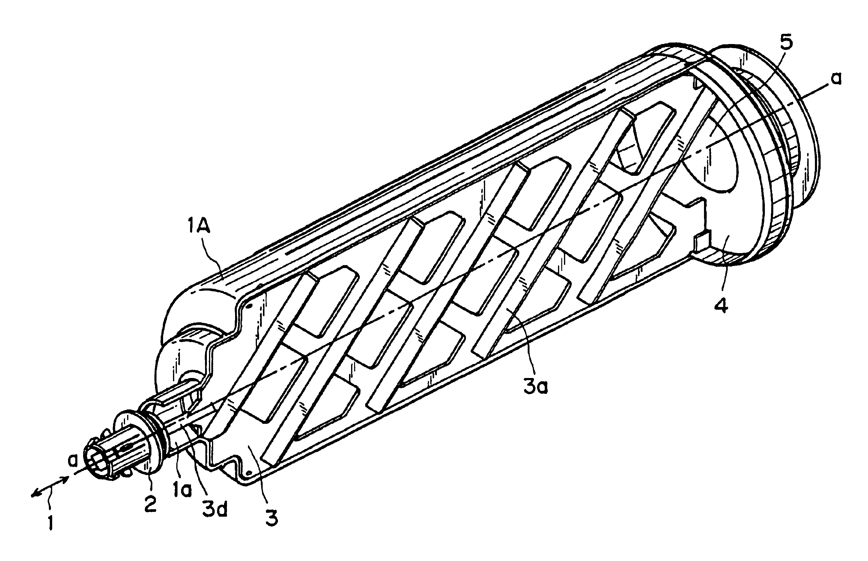
[0061]Next, refering to FIGS. 4, 5(A), and 5(B), the toner supply container in the first embodiment of the present invention will be described. FIG. 4 is a partially broken perspective view of the toner supply container in the first embodiment of the present invention. FIG. 5(A) is a sectional view of the toner supply container, as seen from the front side of the copying machine, and FIG. 5(B) is a plan view of the toner supply container, as seen from the plane A—A in FIG. 5(A).

(Toner Supply Container)

[0062]The toner supply container 1 is structured so that it is mounted into the image forming apparatus main assembly by a user, in the direction virtually parallel to the lengthwise direction of the main body of the container, from the sealing member 2 side of the container. When removing the toner supply container 1, the toner supply container 1 is pulled out of the apparatus main assembly in the direction reverse to the direction in which it was mounted.

[0063]As shown ...

embodiment 2

(Embodiment 2)

[0140]Referring to FIGS. 16(A), 16(B), and 16(C), the second embodiment will be described.

[0141]In these Figures, the inclined projections 3a on the opposite sides of the plate-like portions are in a mirror symmetry relationship with respect to a rotation axis a—a of the toner bottle 1A.

[0142]In a conventional example in which the toner is discharged by rotating the toner bottle 1A, the rotational direction of the toner bottle 1A is determined as being one direction, for discharging the toner (supply).

[0143]In the case of the conventional toner bottle having the helical rib on the inner surface of the toner bottle, the toner can be supplied only when the bottle is rotated in one predetermined direction.

[0144]However, in the case of the toner supply container 1 of this invention, the structure shown in FIG. 16 is possible in which the inclined projections 3a are arranged in a mirror symmetrical fashion. With this arrangement, the toner can be discharged by rotation in e...


PUM


Abstract

A toner supply container detachably mountable to an image forming apparatus, includes a main body for accommodating toner; an opening for permitting discharge of the toner from the main body; a rotatable feeding member, provided in the main body, for feeding the toner by rotation thereof; wherein the feeding member including a lift portion for lifting the toner in the main body, a guiding portion for guiding the toner lifted by the collecting portion downwardly toward the opening, and a falling portion for letting the toner lifted by the lifting portion fall without feeding it toward the opening with rotation of the feeding member.

Description

CROSS-REFERENCE TO RELATED APPLICATION[0001]This application is a divisional application of application Ser. No. 10 / 076,455, filed Feb. 19, 2002.FIELD OF THE INVENTION AND RELATED ART[0002]The present invention relates to an image forming apparatus employing an electrophotographic image formation method or an electrostatic recording method, and a toner supply container used with such an image forming apparatus. In particular, it relates to such an image forming apparatus as a copying machine, a printer, a facsimile machine, or the like and a toner supply container used with such an image forming apparatus.[0003]In an image forming apparatus such as an electrophotographic copying machine, a printer, or the like, microscopic powder of toner has been used as developer. As the developer in an image forming apparatus is consumed, toner is supplied to the image forming apparatus with the use of a toner supply container.[0004]Since toner is in the form of microscopic powder, there has been...

Claims


Application Information

Patent Timeline
Patent Type & Authority Patents(United States)
IPC IPC(8): G03G15/08G03G15/00
CPCG03G15/0868G03G15/0872G03G2215/0665G03G2215/0668G03G2215/0692G03G2215/085Y10S222/01A41C3/065A41C3/0085
Inventor YAMADA, YUSUKEBAN, YUTAKATAZAWA, FUMIOMINAGAWA, HIRONORI
Owner CANON KK
Why Eureka
Try Eureka