
High-frequency signal transmission apparatus and electronic tuner using the same

a transmission apparatus and high-frequency technology, applied in multi-frequency-changing modulation transmission, television system scanning details, television systems, etc., can solve the problems of large power consumption, small amplitude that a single active element can handle, and large power consumption, and achieve high output impedance

Inactive Publication Date: 2005-09-13
PANASONIC CORP
View PDF10 Cites 4 Cited by
  • Summary
  • Abstract
  • Description
  • Claims
  • Application Information

AI Technical Summary

Benefits of technology

"The patent describes a high-frequency signal transmission apparatus that includes a mixer, a matching circuit, a band-pass filter, and an intermediate-frequency amplifier. These components are all balanced circuits connected by a balanced line. The technical effect of this design is that it allows for the efficient transmission of high-frequency signals with low signal loss and improved signal quality. Additionally, the matching circuit ensures that the impedance of the circuit is equal to the impedance of the band-pass filter, which further enhances the signal transmission."

Problems solved by technology

However, there is a problem.
Because the HF signal transmission apparatus for use in such a conventional electronic tuner is made of components having a low impedance of 50 Ω, a large current flowing therethrough causes large power consumption.
Further, because all the components are made of unbalanced circuits, an amplitude that a single active element can handle is small.
This results in a problem of large power consumption.

Method used


Image

  • High-frequency signal transmission apparatus and electronic tuner using the same
  • High-frequency signal transmission apparatus and electronic tuner using the same
  • High-frequency signal transmission apparatus and electronic tuner using the same

Examples


Embodiment Construction

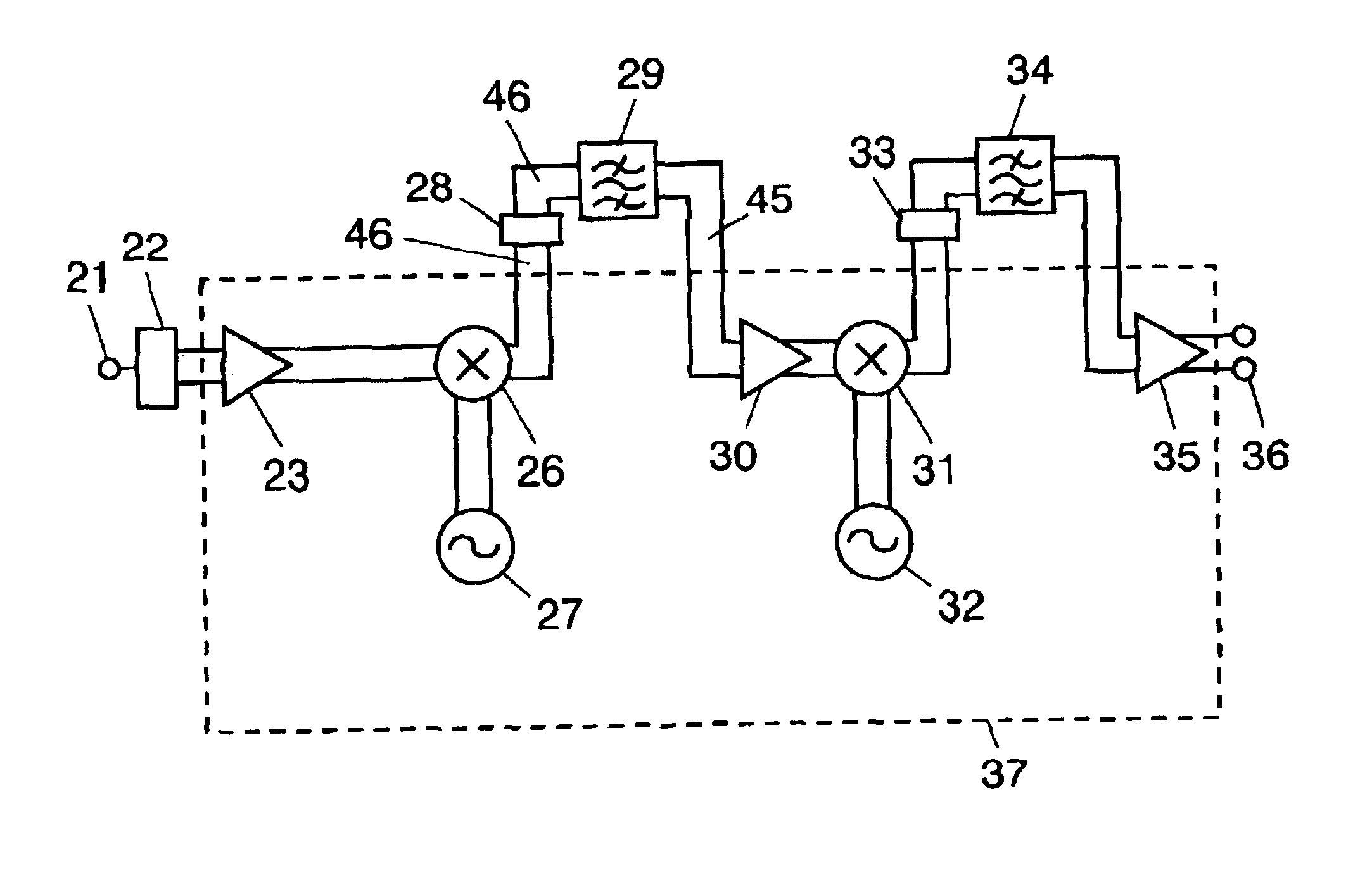
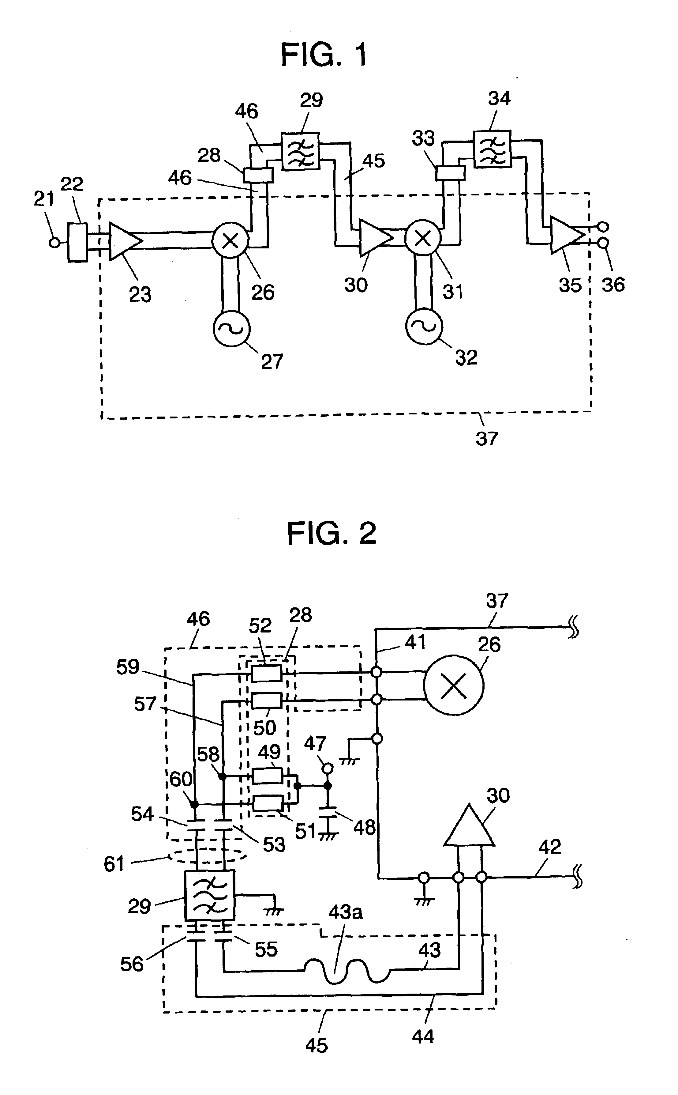
[0030]An exemplary embodiment of the present invention is demonstrated hereinafter with reference to the accompanying drawings. FIG. 1 is a block diagram of an electronic tuner in accordance with the exemplary embodiment of the present invention. This is an example of an electronic tuner using a high-frequency (HF) signal transmission apparatus in accordance with the present invention.

[0031]With reference to FIG. 1, HF signals modulated by television signals are supplied into input terminal 21. These HF signals include signals that are transmitted through a plurality of television broadcast channels and have different frequencies. The frequencies of the television broadcast channels of these HF signals to be received range from approx. 50 to 900 MHz. Connected to this input terminal 21 is unbalanced-to-balanced converter 22. This unbalanced-to-balanced converter 22 converts a signal that is unbalanced and has an impedance of 75 Ω into a signal that is balanced and has a impedance of...


PUM


Abstract

An electronic tuner has an input terminal, a mixer receiving the signal fed into the input terminal, a matching circuit connected to an output of the mixer, a band-pass filter connected to an output of this matching circuit, an intermediate-frequency (IF) amplifier connected to an output of the band-pass filter, and an output terminal receiving output of the IF amplifier. These circuits are composed of balanced circuits and connected by balanced lines. The mixer has a high output impedance. For the matching circuit, the impedance of the matching circuit at the band-pass filter side is equal to the impedance of the band-pass filter at the matching circuit side. This structure can realize an electronic tuner having low power consumption.

Description

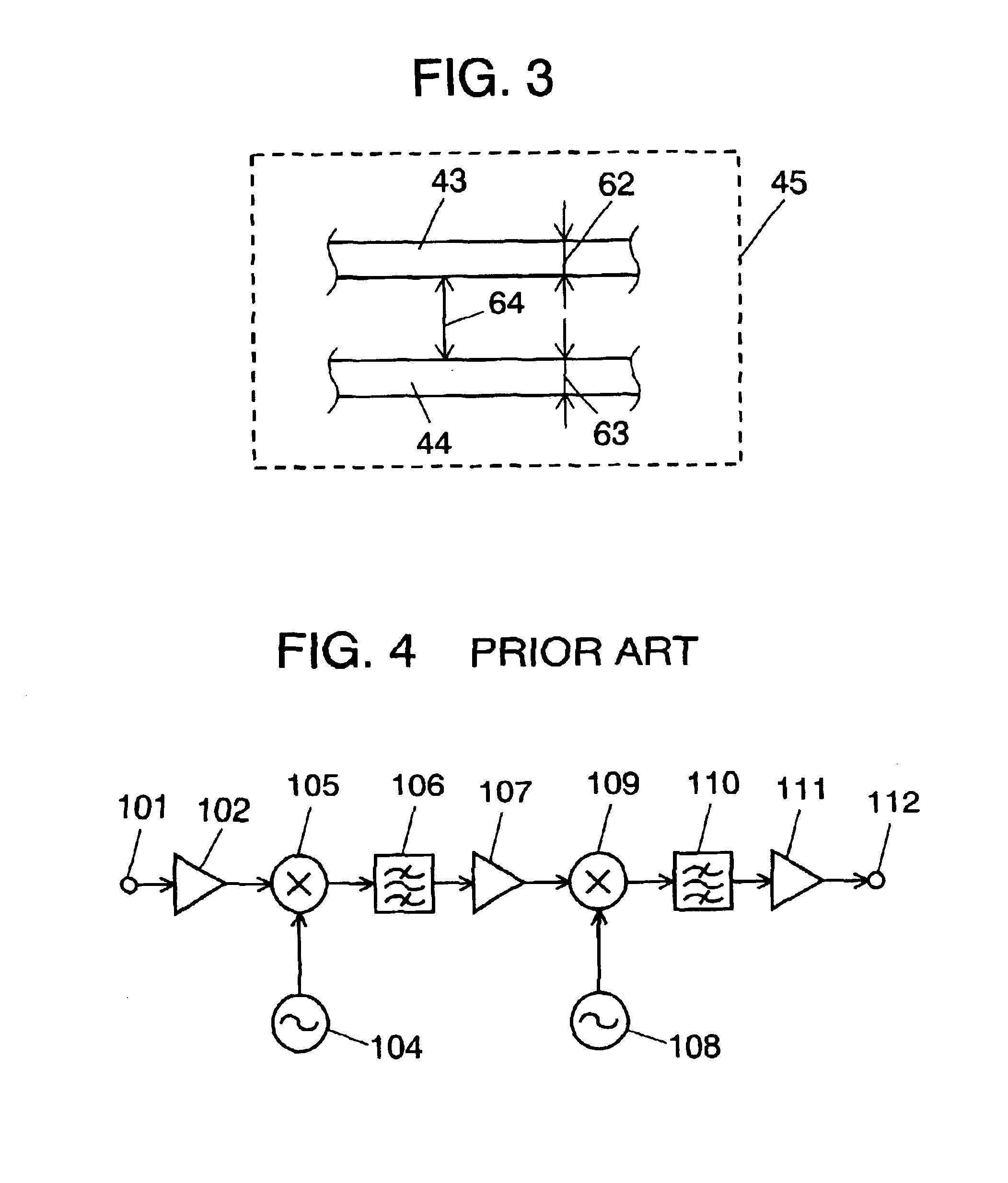
FIELD OF THE INVENTION[0001]The present invention relates to a high-frequency signal transmission apparatus and an electronic tuner using the same.BACKGROUND OF THE INVENTION[0002]A conventional electronic tuner is described hereinafter with reference to FIG. 4, as an example of a conventional high-frequency signal transmission apparatus.[0003]FIG. 4 shows a conventional electronic tuner. In the drawing, high-frequency (HF) signals that have been modulated by television signals are fed into low-noise HF amplifier 102, via input terminal 101. Fed into mixer 105 are the output of HF amplifier 102 and the output of local oscillator 104. The output of this mixer 105 is fed into band-pass filter 106. In turn, the output of band-pass filter 106 is fed into intermediate-frequency (IF) amplifier 107. The output of this IF amplifier 107 and the output of local oscillator 108 are fed into mixer 109. In turn, the output of this mixer 109 is fed into band-pass filter 110. IF amplifier 111 ampli...

Claims


Application Information

Patent Timeline
Patent Type & Authority Patents(United States)
IPC IPC(8): H03D7/00H03D7/16H03H7/42H04B1/16H04B1/26H04N5/44
CPCH03D7/161
Inventor SUZUKI, MASANORITERAO, ATSUHITOASAYAMA, SANAE
Owner PANASONIC CORP
Learn More