Traveling yarn tension compensating system

a tension compensating system and travel yarn technology, applied in the direction of transportation and packaging, thin material processing, filament processing, etc., can solve the problems of equipment stopping, product or portion of product may not be usable, etc., and achieve the effect of greater friction resistance, less friction resistance, and increased initial tension

Inactive Publication Date: 2005-09-20
ZOLLINGER RICHARD V
View PDF18 Cites 13 Cited by
  • Summary
  • Abstract
  • Description
  • Claims
  • Application Information

AI Technical Summary

Benefits of technology

[0008]Preferably, the element on which the yarn engaging surface is formed is freely movable in a substantially vertical direction in response to the tension in the traveling yarn entering the system. This is accomplished in the preferred embodiment by the movable element on which the yarn engaging surface is formed being a movable slide positioned for movement in a generally vertically extending slide guide, with the guide being at an inclination to the vertical in a direction inclined toward the yarn guiding device to which the yarn is traveling, allowing the guided element to respond more freely to an increase in tension in the traveling yarn.

Problems solved by technology

Variations in yarn tension can result in undesirable variations in the product produced with the yarn, thereby effecting the quality of the product.
In severe cases, the product or portions of the product may not be usable or the equipment may be stopped because of a wide tension variation.

Method used


Image

  • Traveling yarn tension compensating system
  • Traveling yarn tension compensating system
  • Traveling yarn tension compensating system

Examples


Embodiment Construction

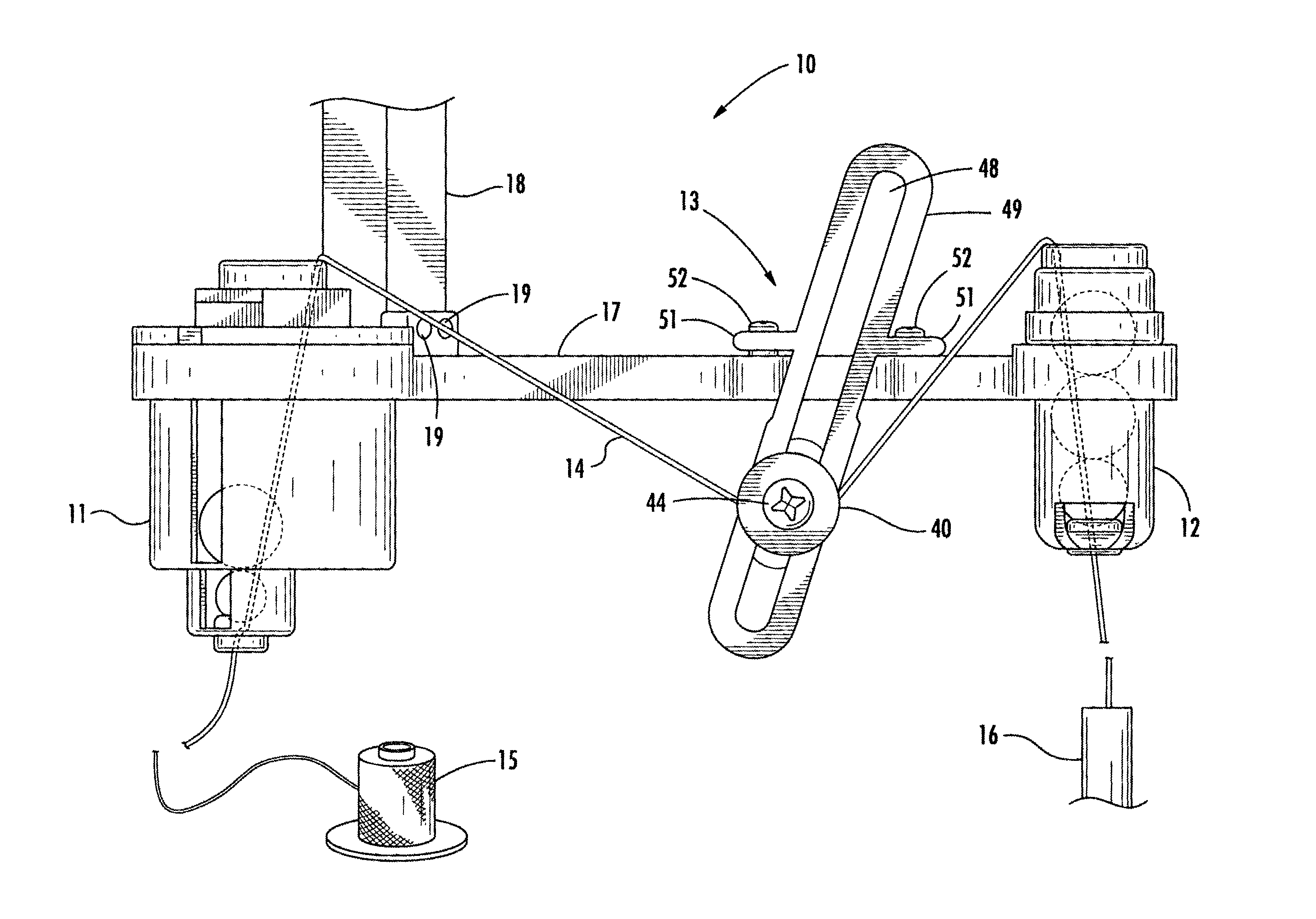
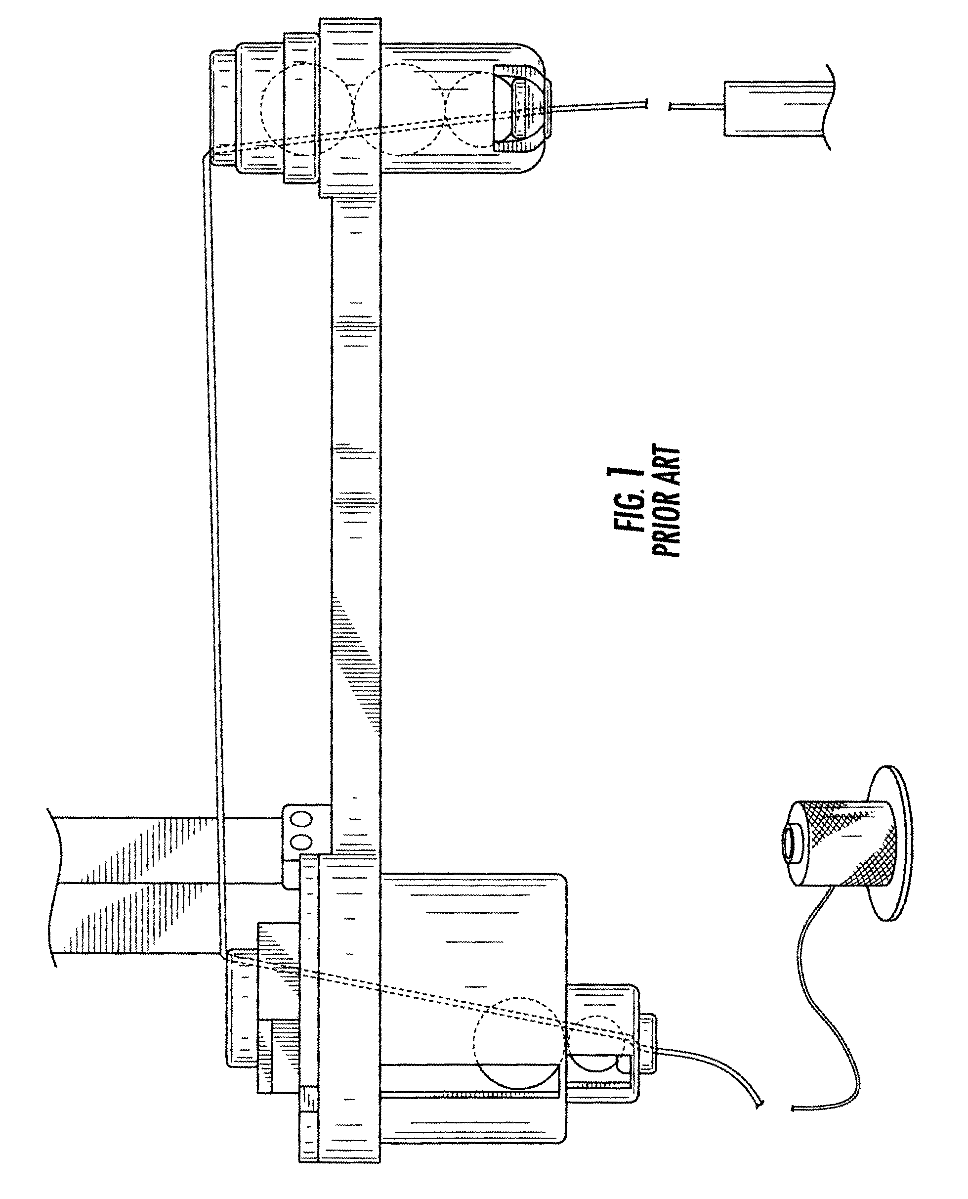
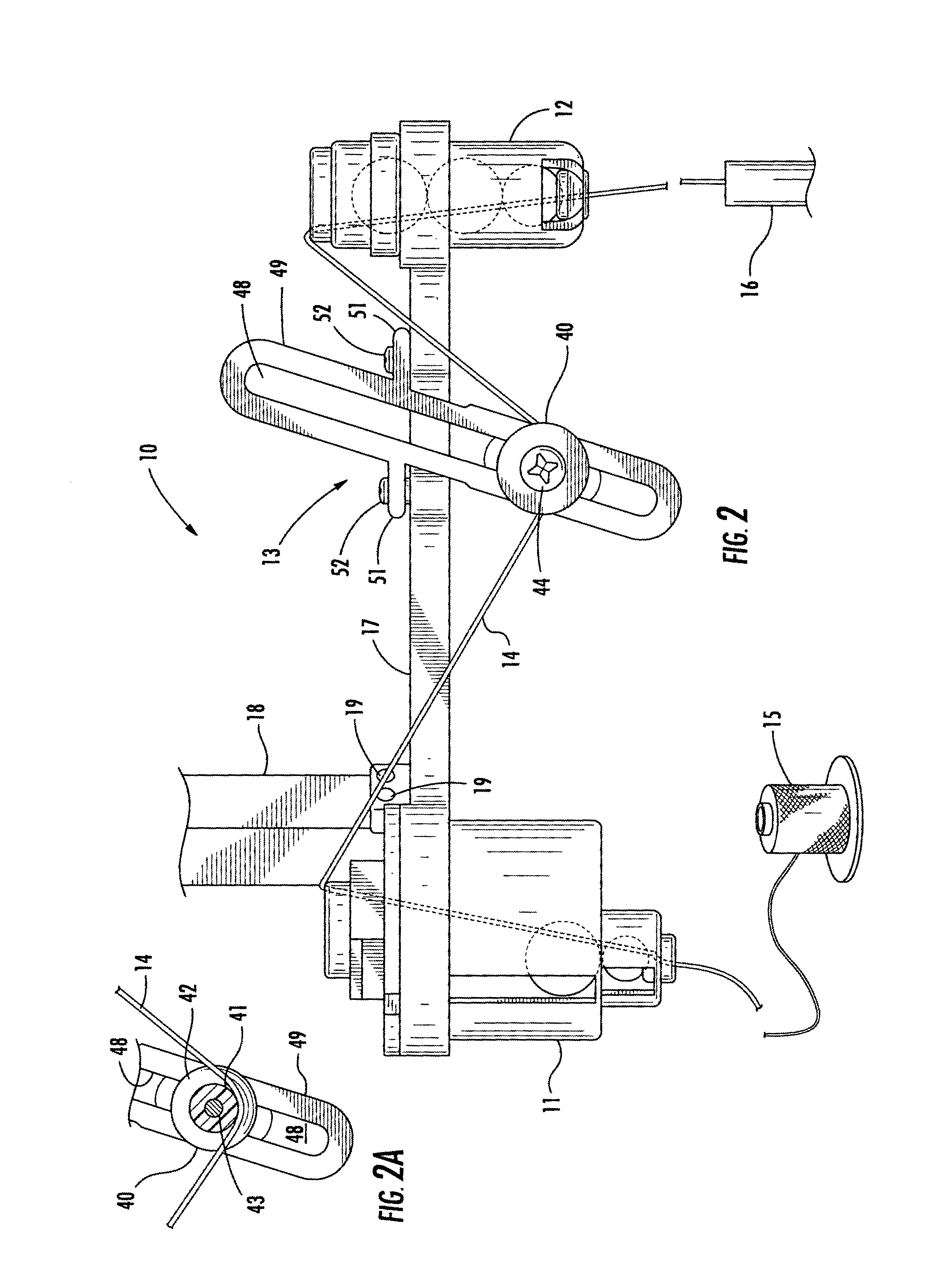
[0027]The preferred embodiment of the traveling yarn tension compensating system 10 of the present invention illustrated in the accompanying drawings includes a pair of spaced yarn guiding devices 11 with a yarn tension compensating device 13 disposed therebetween. The system is located in the line of supply of a yarn from a supply package 15 to and through the system 10 and into a feed tube leading to a textile machine, such as a cabler. However, the system 10 of the present invention is applicable to use with various other types of textile machines that utilize yarn in the manufacture of a textile product.

[0028]The yarn guiding devices 11 and 12 and the yarn tension compensating device 13 are mounted on a frame 17 that is attached to a structural component 18 of the textile machine by nut and bolts 19 or any other attachment means. The frame 17 supports the yarn guiding devices 11 and 12 and the tension compensating device 13 in generally horizontal alignment.

[0029]One of the guid...


PUM


Abstract

A traveling yarn tension compensating system having a pair of vertically disposed, horizontally spaced ball-type yarn tensioning units and a yarn tension compensating device disposed therebetween. The device has a yarn engaging element with a yarn engaging surface that is downwardly convex for engaging a yarn thereunder. The surface is fixed so as not to rotate or otherwise move in the direction of travel of the yarn and is made of a material that imposes a tension increasing frictional drag on the traveling yarn. The surface engaging element is mounted to be freely movable vertically in response to tension in the traveling yarn. The convex shape of the yarn engaging surface results in a greater extent of surface engagement of the yarn when the surface engaging element is in a lower position resulting from lesser tension in the yarn and at which position it deflects the yarn downwardly over the yarn guides. When there is greater tension in the traveling yarn, the yarn raises the surface engaging element to upper positions at which the extent of surface contact by the surface and the yarn guides is less.

Description

FIELD OF THE PRESENT INVENTION[0001]The present invention relates to maintaining uniform tension in a traveling yarn being fed to a machine for manufacturing textiles.BACKGROUND OF THE PRESENT INVENTION[0002]Maintaining uniform tension in yarn being fed to machines utilized in the manufacturing of textile products has long been an important factor effecting the productivity of the manufacturing process and the quality of the textile product produced. Variations in yarn tension can result in undesirable variations in the product produced with the yarn, thereby effecting the quality of the product. In severe cases, the product or portions of the product may not be usable or the equipment may be stopped because of a wide tension variation.[0003]Many attempts have been made to control yarn tension so that a relatively uniform yarn tension is present in the yarn when it is fed to a yarn processing machine. The best of these has proven to be ball-type yarn tensioning units, such as disclo...

Claims


Application Information

Patent Timeline
Patent Type & Authority Patents(United States)
IPC IPC(8): B65H59/36B65H59/10B65H59/22B65H59/24
CPCB65H59/22B65H59/24B65H59/36B65H2701/31
Inventor ZOLLINGER, RICHARD V.
Owner ZOLLINGER RICHARD V
Why Eureka
Try Eureka