
Braking system for vehicle provided with ABS or an anti-skid protection system

a technology of anti-skid protection and braking system, which is applied in the direction of braking system, mechanical equipment, transportation and packaging, etc., can solve the problems of error in computing the reference speed, no longer being able to control the corresponding assigned wheels, and unable to calculate the reference speed. , to achieve the effect of improving driving safety

Inactive Publication Date: 2005-09-20
KNORR BREMSE SYST FUR SCHIENENFAHRZEUGE GMBH
View PDF32 Cites 6 Cited by
  • Summary
  • Abstract
  • Description
  • Claims
  • Application Information

AI Technical Summary

Benefits of technology

[0008]To prevent faulty rotational wheel speed signals from falsifying the reference speed value, conventional algorithms for computing the reference speed have a “detection” of faulty signals, but a reliable detection of all possible faults requires very high expenditures. In addition, faults may have an effect on the calculation of the reference speed already during the fault disclosure time such that the braking force control is affected.
[0012]In the “redundant” detection of the rotational wheel speed, at least two rotational wheel speed signals of a wheel or of a wheel group are always included in the control. The wheel or the wheel group can therefore still be controlled when one of the two rotational wheel speed signals fails or has interference. This significantly improves the driving safety.
[0014]According to a further development of the invention, a control unit is provided for the plausibility check of the rotational wheel speed signals supplied by the rotational wheel speed sensors. The rotational wheel speed signals are checked particularly with respect to “signal peaks” which are based on interference. In the control unit, an analyzing algorithm is implemented which recognizes “faulty” rotational wheel speed signals and optionally excludes them for calculating the reference speed. All detected rotational wheel speed signals can be analyzed in a common arithmetic unit, can be compared with one another and can be checked with respect to plausibility. This permits the detection of “implausible” or “disturbed” rotational wheel speed signals and therefore increases the safety of the entire braking system.

Problems solved by technology

When the measured rotational wheel speed signals are faulty, for example, as a result of electromagnetic interference fields and / or system-caused measuring errors, which result in “peaks” in the speed course or acceleration course of the measuring signals, errors may then also occur when computing the reference speed.
A “false” reference speed may result in errors in controlling the braking force of the entire vehicle.
This is problematic particularly in the case of those vehicles which only have an independent system for the braking force control.
If one rotational wheel speed sensor fails, the assigned wheels can no longer be controlled corresponding to the existing rotational wheel speed.
To prevent faulty rotational wheel speed signals from falsifying the reference speed value, conventional algorithms for computing the reference speed have a “detection” of faulty signals, but a reliable detection of all possible faults requires very high expenditures.
In addition, faults may have an effect on the calculation of the reference speed already during the fault disclosure time such that the braking force control is affected.
Even when only one arithmetic unit, that is, one brake control unit, is provided, an error occurring in the detection of the rotational wheel speed may have an effect on maximally half of the brakes.

Method used


Image

  • Braking system for vehicle provided with ABS or an anti-skid protection system
  • Braking system for vehicle provided with ABS or an anti-skid protection system
  • Braking system for vehicle provided with ABS or an anti-skid protection system

Examples


Embodiment Construction

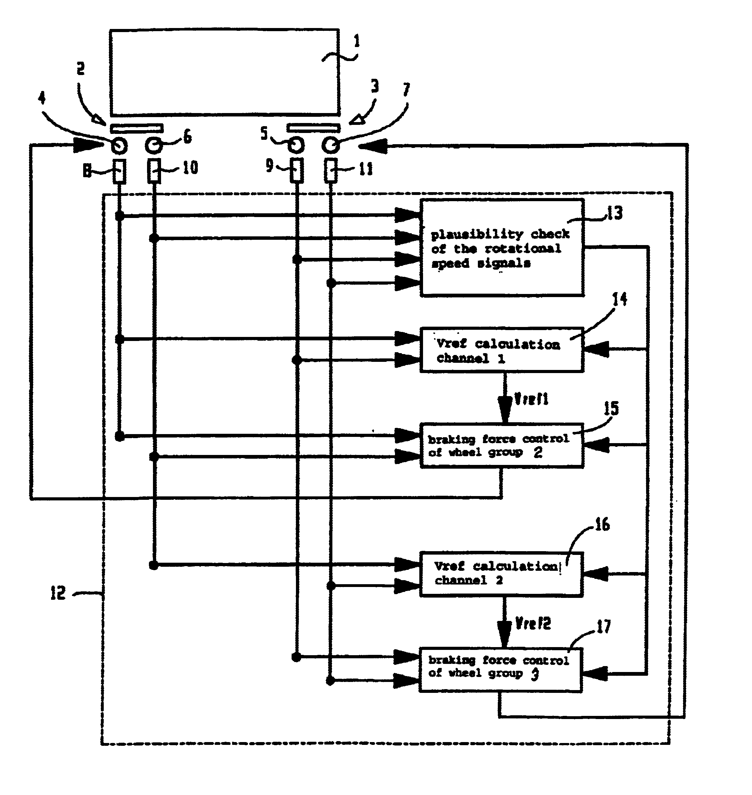
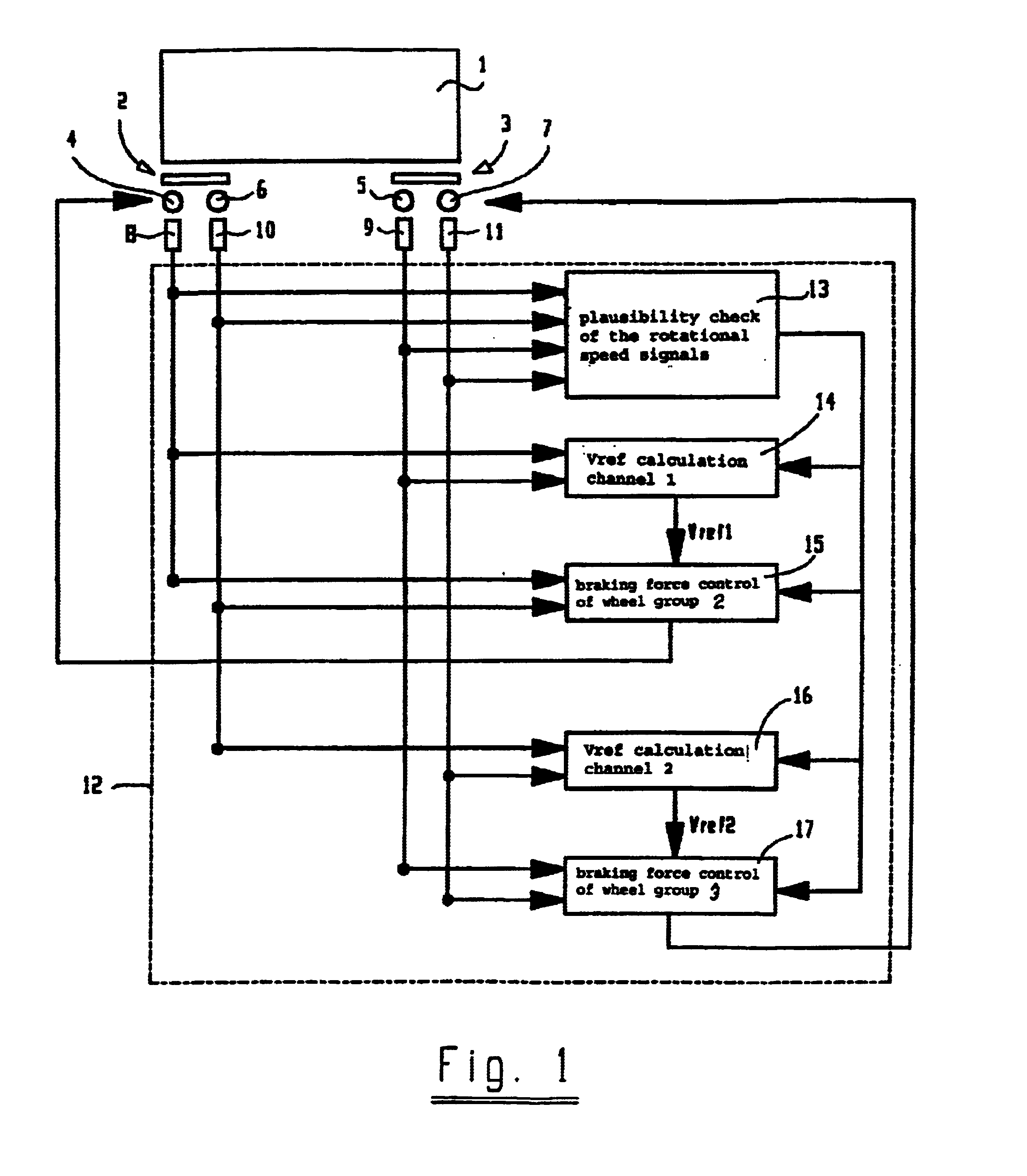
[0027]FIG. 1 illustrates a vehicle 1 with a first wheel group 2 and a second wheel group 3. The two wheel groups 2, 3 may, for example, be bogies of a rail vehicle and each has a first axle 4, 5 and a second axle 6,7 respectively. One rotational wheel speed sensor 8-11 respectively is assigned to the axles 4-7.

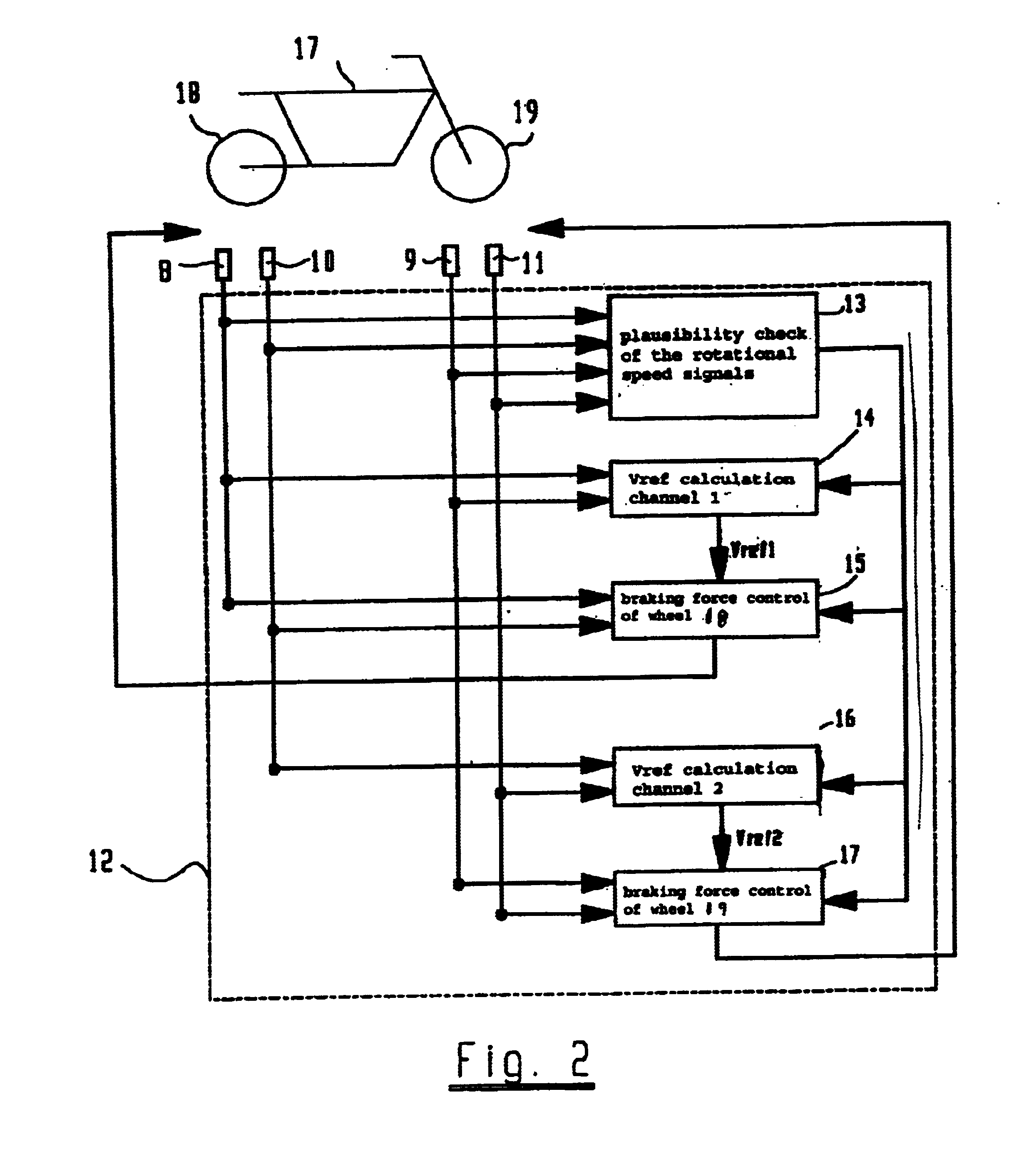
[0028]The rotational wheel speed sensors 8-11 are connected with a brake control unit 12 which is shown here only schematically. In the brake control unit 12, a plausibility check 13 is implemented which is to detect faulty or “disturbed” rotational wheel speed signals and optionally separate them.

[0029]The brake control unit 12 also has two channels for the separate or independent calculation of one reference speed respectively approximated to the actual vehicle speed. Brakes (not shown) provided in the vehicle are assigned to a first or to a second group. Here, the first group is formed by the brakes of the first wheel group 2, and the second group is formed by the brakes of...


PUM


Abstract

The general principle underlying the invention is a braking system that is provided with an arithmetic unit with at least two independent channels for determining the reference speeds approximated to the actual vehicle speed. The at least two determined reference speeds are used only for regulating a part of the brakes installed in the vehicle.

Description

BACKGROUND AND SUMMARY OF THE INVENTION[0001]The present invention relates to a braking system for vehicles equipped with an ABS system or an antiskid protection system.[0002]An antilock system for a motorcycle is known from German Patent Document 39 31 313 A1, in which a total of only two rotational wheel speed sensors are provided, one sensor being assigned to the front wheel and the other being assigned to the rear wheel. For determining the wheel slip, a reference quantity is determined which is approximated to the course of the vehicle speed and in which case two channels are provided. The two reference speeds are determined on the basis of the assigned wheel speed and a multiplier dependent on the driving condition.[0003]U.S. Patent Document U.S. Pat. No. 5,791,744 A describes an electropneumatic braking system for rail vehicles, in which a “universal unit” is assigned to each car and controls the brakes of the respective car. Such a universal unit consists of an electronic po...

Claims


Application Information

Patent Timeline
IPC IPC(8): B60T8/172B60T8/17B60T8/00B60T8/1761B60T8/66B60T8/88
CPCB60T8/172B60T2250/04Y10S303/09
Inventor MAYER, REINHOLDSCHMID, RALF
Owner KNORR BREMSE SYST FUR SCHIENENFAHRZEUGE GMBH
Learn More