Fluid controlled pumping system and method

a pumping system and fluid control technology, applied in the direction of positive displacement liquid engines, survey, wellbore/well accessories, etc., can solve the problems of progressive cavity pump failure within a relatively short period of time, inability to lubricate the pumping unit, and inability to maintain the pumping unit. , to achieve the effect of increasing the reliability of the pumping unit and decreasing the fluid level

Inactive Publication Date: 2005-09-20
EFFECTIVE EXPLORATION
View PDF48 Cites 27 Cited by
  • Summary
  • Abstract
  • Description
  • Claims
  • Application Information

AI Technical Summary

Benefits of technology

[0010]Another technical advantage of the present invention includes increased reliability of the pumping unit without necessitating costly user intervention. For example, according to one embodiment of the invention, a valve is slidably coupled to the pumping unit, thereby providing upward and downward movement of the valve in response to variations in a fluid level within a fluid cavity. The valve automatically provides recirculation or the return of the pumped fluid to the inlet of the pumping unit to ensure lubrication of the pumping unit in response to decreasing fluid levels within the fluid cavity.

Problems solved by technology

Conventional pumping units, however, suffer several disadvantages.
In the case of the progressive cavity pump, friction caused by the rotation of the rotor relative to the stator without fluid lubrication oftentimes causes the progressive cavity pump to fail within a relatively short period of time.
However, variations in the fluid level proximate to an inlet of the pumping unit may result in an absence of fluid lubrication for the pumping unit.
Additionally, in centrifugal pumping applications, an absence of the fluid to be pumped may cause cavitation.

Method used


Image

  • Fluid controlled pumping system and method
  • Fluid controlled pumping system and method
  • Fluid controlled pumping system and method

Examples


Embodiment Construction

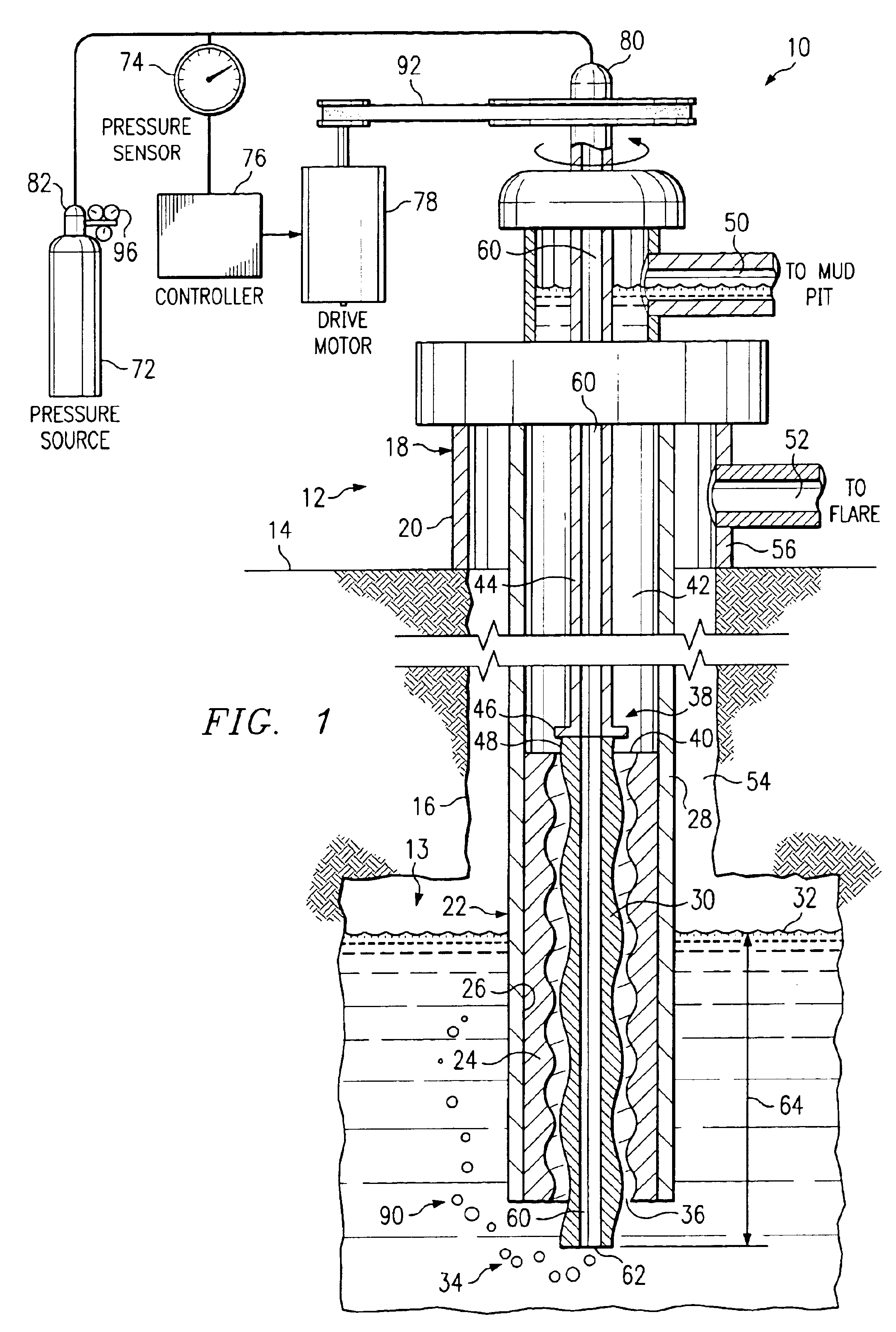
[0017]FIG. 1 is a diagram illustrating a fluid controlled pumping system 10 in accordance with an embodiment of the present invention. In the embodiment of FIG. 1, the system 10 is illustrated in a mining or hydrocarbon production application; however, it should be understood that the system 10 may also be used in other pumping applications. The system 10 includes a pumping unit 12 extending into a fluid cavity 13. The fluid cavity 13 generally includes a fluid to which a compressing, raising, or transferring operation is to be performed. Thus, in the illustrated embodiment, the pumping unit 12 extends downwardly from a surface 14 into a well bore 16. In this embodiment, pumping unit 12 comprises a progressive cavity pump 18; however, it should be understood that other types of pumping units 12 may be used incorporating the teachings of the present invention.

[0018]Pump 18 includes a base portion 20 disposed on the surface 14 and a stator / rotor portion 22 disposed within the well bor...


PUM


Abstract

A fluid level controlled pumping system includes a pumping unit disposed within a fluid cavity. The pumping unit includes an inlet operable to receive a fluid to be pumped from the fluid cavity. The system also includes a valve slidably coupled to the pumping unit. The valve includes a passage for receiving pumped fluid from an outlet of the pumping unit. In response to a decreasing fluid level within the fluid cavity, movement of the valve relative to the pumping unit aligns the passage with a port of the pumping unit to recirculate the pumped fluid from the outlet to the inlet.

Description

CROSS-REFERENCE TO RELATED APPLICATION[0001]This application is a continuation of U.S. application Ser. No. 09 / 841,773 filed Apr. 24, 2001 U.S. Pat. No. 6,604,910 and entitled “Fluid Controlled Pumping System and Method”.TECHNICAL FIELD OF THE INVENTION[0002]This invention relates in general to the field of fluid pumping systems and, more particularly, to a fluid controlled pumping system and method.BACKGROUND OF THE INVENTION[0003]Pumping units are used in a variety of applications for compressing, raising, or transferring fluids. For example, pumping units may be used in municipal water and sewage service applications, mining and / or hydrocarbon exploration and production applications, hydraulic motor applications, and consumer product manufacturing applications. Pumping units, such as progressive cavity pumps, centrifugal pumps, and other types of pumping devices, are generally disposed within a fluid and are used to compress or increase the pressure of the fluid, raise the fluid ...

Claims


Application Information

Patent Timeline
Patent Type & Authority Patents(United States)
IPC IPC(8): F04C13/00E21B47/00F04C14/08F04C14/28
CPCE21B47/0007F04C13/008F04C14/08F04C14/28E21B47/008
Inventor ZUPANICK, JOSEPH A.RIAL, MONTY H.
Owner EFFECTIVE EXPLORATION
Why Eureka
Try Eureka