Power tool having a receptacle for securing a tool

a technology of power tools and receptacles, which is applied in the field of receptacles, can solve the problems of known receptacles for engagement between the tool and the drive shaft, tend to wear out, etc., and achieve the effects of reliable engagement, high torque and/or high surface pressur

Inactive Publication Date: 2005-09-20
C & E FEIN GMBH & CO KG
View PDF13 Cites 121 Cited by
  • Summary
  • Abstract
  • Description
  • Claims
  • Application Information

AI Technical Summary

Benefits of technology

[0009]It is a second object of the invention, to create an improved receptacle in which the danger of wear out of the receiving opening is reduced and a transmission of high torques is guaranteed also in long-term operation.
[0025]By using such an adapter, it is possible to use tools, that have already been provided with the receptacle according to the invention on power tools, with drive shafts that have a known securing section. In that way, it is ensured that not all power tools already acquired by users need to be exchanged, if the new tools with the securing section according to the invention are to be used to this end.

Problems solved by technology

It has turned out to be disadvantageous that the known receptacle for engagement between the tool and the drive shaft, in particular for such oscillatingly driven tools, tends to wear out after longer operation under high load.

Method used


Image

  • Power tool having a receptacle for securing a tool
  • Power tool having a receptacle for securing a tool
  • Power tool having a receptacle for securing a tool

Examples


Embodiment Construction

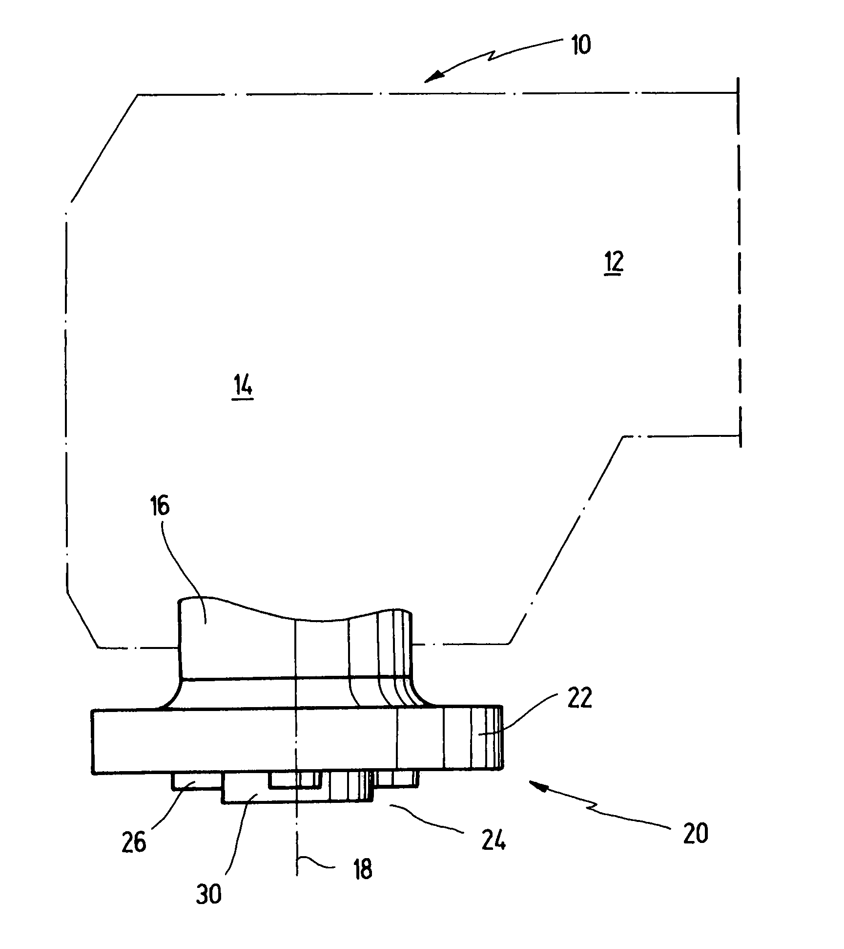
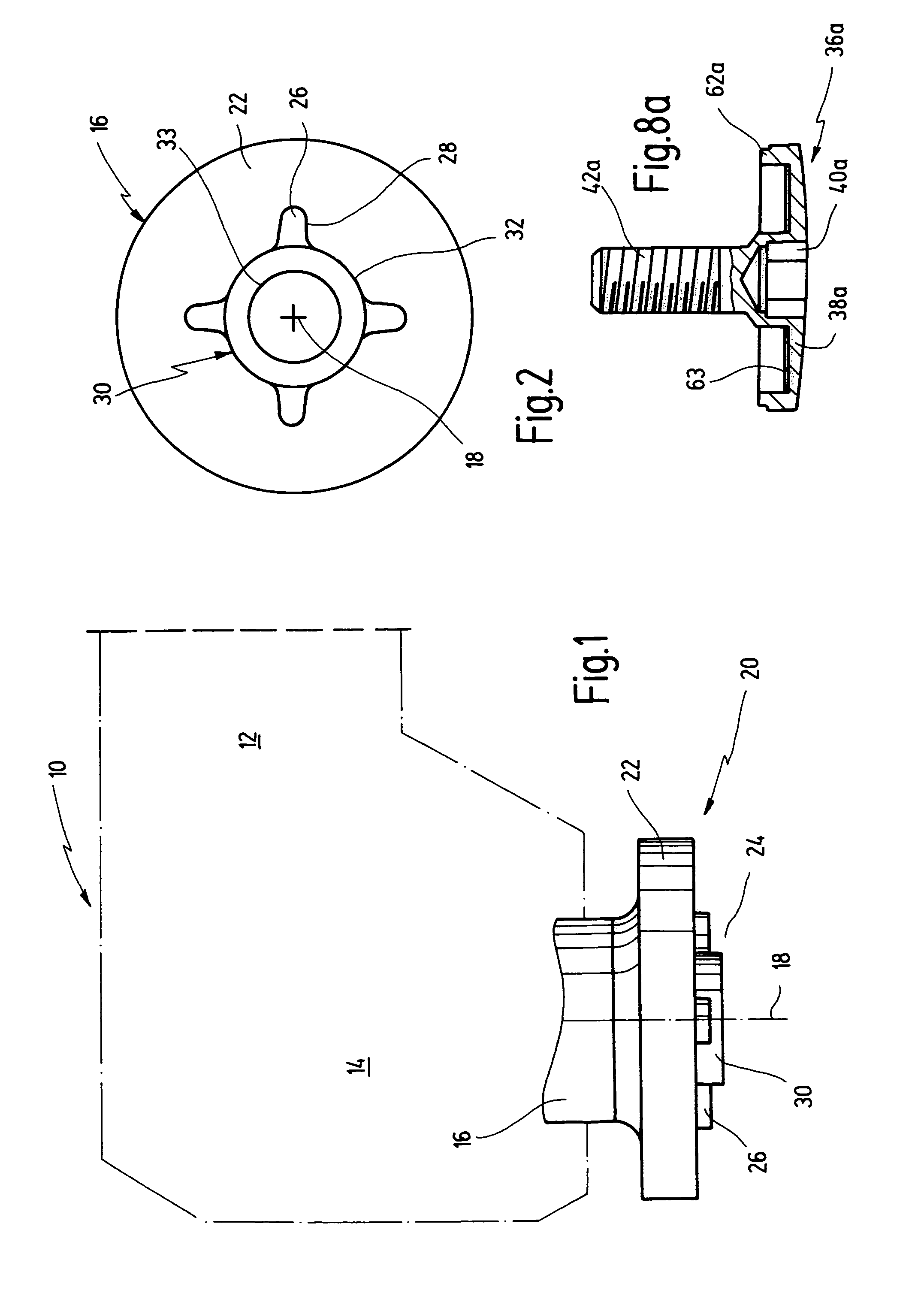
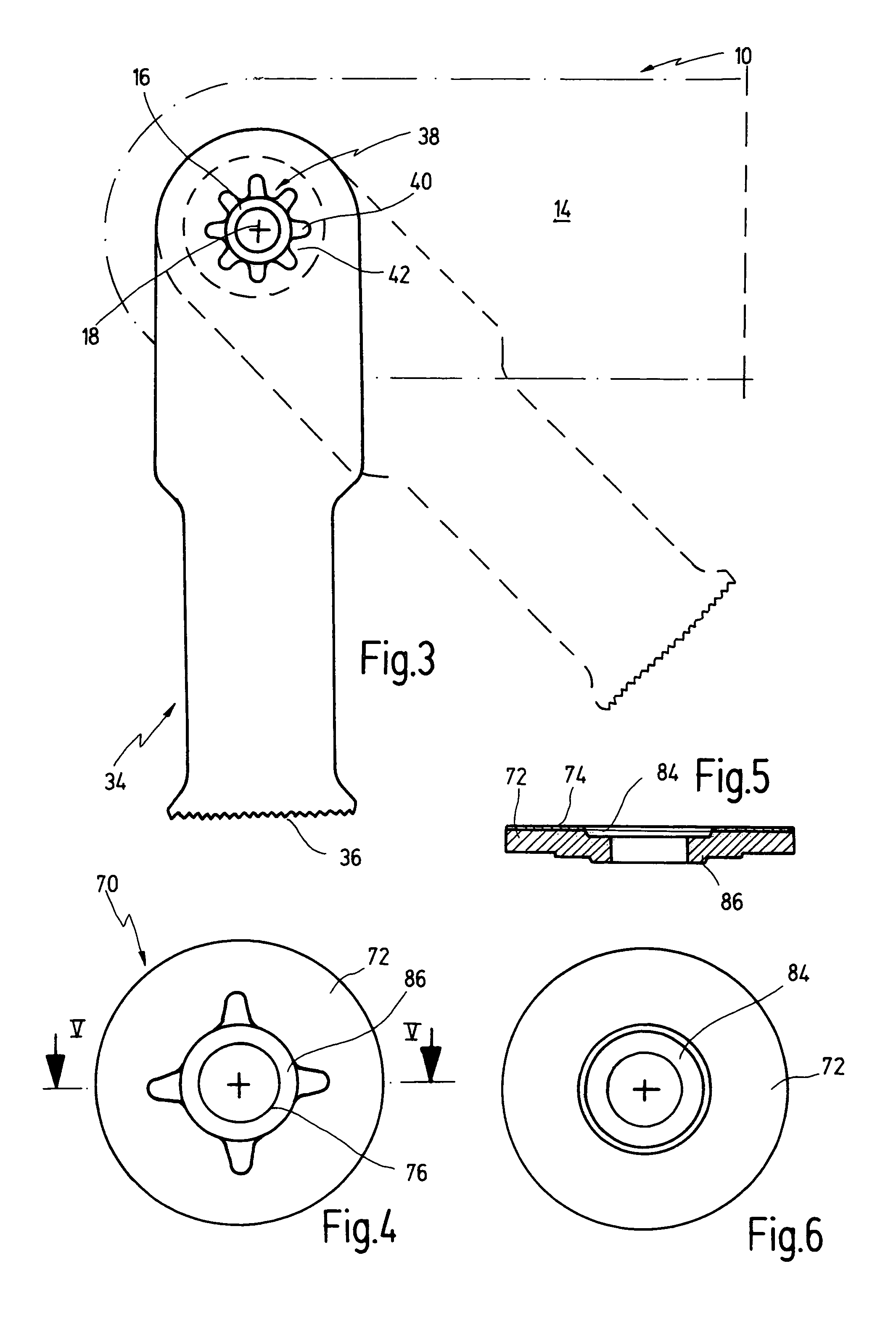
[0038]In FIG. 1, a power tool, which is altogether designated with the numeral 10, is shown in a very schematic fashion. Power tool 10 comprises a drive that is indicated with the numeral 12, which drives a drive shaft 16 via a gear that is indicated with 14. Drive shaft 16 comprises tool support 20 having retaining flange 22 that serves to axially support a tool that can be secured onto a securing section 24 protruding outwardly there from. The retaining flange 22 has an outer diameter that is larger than the diameter of securing section 24. On securing section 24 of drive shaft 16, a tool 34 (shown in FIG. 3) can be mounted and can be fixed to the drive shaft 16 by a screw-connection.

[0039]In the present case, power tool 10 is configured such that drive shaft 16 is driven by gear 14 in an oscillating movement back and forth about its longitudinal axis or center axis 18 with a high frequency of e.g. approximately 5000 to 30,000 oscillations per minute and with a small pivot angle o...


PUM


Abstract

A power tool having a receptacle for securing a tool to a drive shaft thereof is disclosed. The receptacle comprises a receiving opening, preferably being arranged on the tool. The receiving opening engages a securing section preferably being provided in a raised fashion on the drive shaft of the power tool, thereby effecting a positive fit. The securing section comprises a plurality of rounded tips arranged at even radial distances from said longitudinal axis, at angular intervals between each other, each rounded tip having a pair of lateral flanks extending from a common apex toward an intermediate section connecting lateral flanks of a pair of adjacent rounded tips. Preferably the receiving opening comprises a number of rounded tips which is twice the number of rounded tips provided on the raised section.

Description

RELATED APPLICATIONS[0001]This application is a continuation-in-part application of U.S. patent application Ser. No. 10 / 003,645 filed Nov. 2, 2001, now U.S. Pat. No. 6,796,888 claiming priority of German patent application serial number 100 61 559.7 filed on Dec. 7, 2000 which is incorporated herein by reference.BACKGROUND OF THE INVENTION[0002]The invention relates to a receptacle for securing a tool to a drive shaft of a power tool, a receiving opening being arranged on the tool or on the drive shaft, and a center axis of the drive shaft extending there through, the opening co-acting with a suitably formed securing section arranged in a raised fashion at the other one of the two elements, in order to form a positive engagement for transmitting a torque between the drive shaft and the tool.[0003]The invention further relates to a suitable adapter that can be used, if the receiving opening and the securing section of the tool or of the drive shaft are of different shapes.[0004]A rec...

Claims


Application Information

Patent Timeline
Patent Type & Authority Patents(United States)
IPC IPC(8): B23D61/00B23D61/02B24B23/02B24B23/00B24B45/00B23B31/00B27B5/32B27B5/00
CPCB23B31/008B23D61/006B23D61/025B24B23/02B24B45/006B27B5/32B23B2231/48
Inventor JASCH, MICHAELBORTZ, JOERG
Owner C & E FEIN GMBH & CO KG
Why Eureka
Try Eureka