
Contact type pulse measurement device

a pulse measurement and contact technology, applied in the field of contact type pulse measurement devices, can solve the problems of electric wire shaking or twisted, device movement, electric wire may be exposed partially,

Inactive Publication Date: 2005-09-20
BOSON TECH
View PDF7 Cites 8 Cited by
  • Summary
  • Abstract
  • Description
  • Claims
  • Application Information

AI Technical Summary

Benefits of technology

"The present invention provides a solution to the shortcomings of prior-art electrode sensors by providing a contact type of pulse measurement device that only requires one hand to grip an electrode sensor. The device comprises a first active sensor electrode and a second sensor electrode having opposite polarities with each other, and the two electrodes are connected to a pulse measurement device by conductive wires. The device also includes a bio-potential sensor, a bio-signal measurement, and a buffer / balance circuit that provides a circuit with a self common point electrode potential. The device can detect biological signals using the first and second electrodes and the common point electrode. This invention allows users to measure pulses with a single hand and provides greater flexibility in gripping and adjusting gestures."

Problems solved by technology

However, the device using a clamp or a bracelet is movable and thus the electric wire may be exposed partially.
The device will be moved and the electric wire will be shaken or twisted when the exerciser is doing exercises.
The displacement of the device and the interference of the conductive wire according to the foregoing phenomenon directly affect the computation for measuring the heartbeat rate with respect to the microprocessor of the system, so that the measured value of the heartbeat rate may be inaccurate and results in a large error.
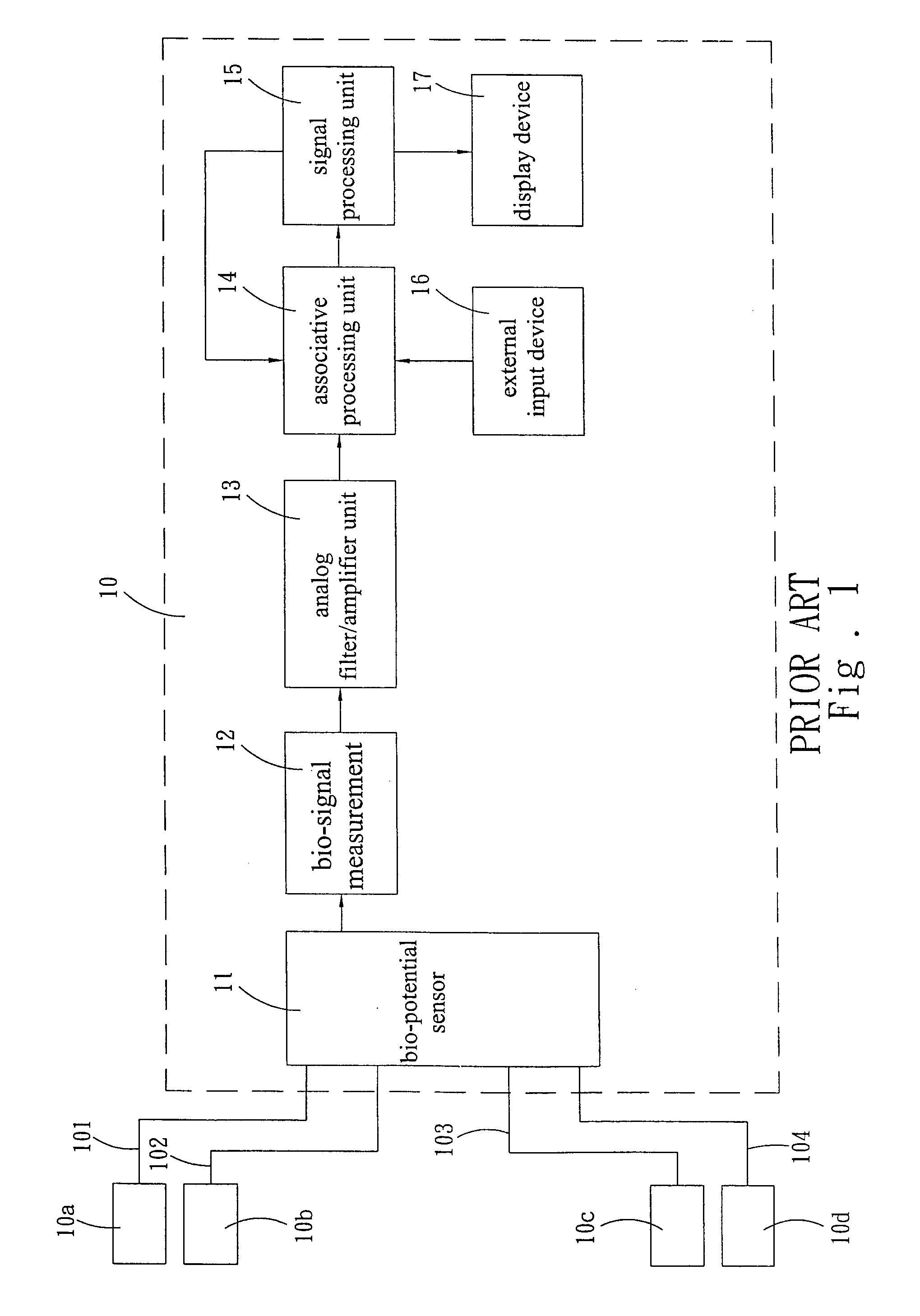
However, a hand is holding the first active sensor electrode 10a and the first common point sensor electrode 10b (or the second active sensor electrode 10d and the second common point sensor electrode 10c), and it will reduce the contact area of the electrode sensor and affect the reliability of receiving the signals.

Method used


Image

  • Contact type pulse measurement device
  • Contact type pulse measurement device
  • Contact type pulse measurement device

Examples


Embodiment Construction

[0011]To understand the objective of the invention, its structure, innovative features, and performance, we use a preferred embodiment and the attached drawings for the detailed description of the invention.

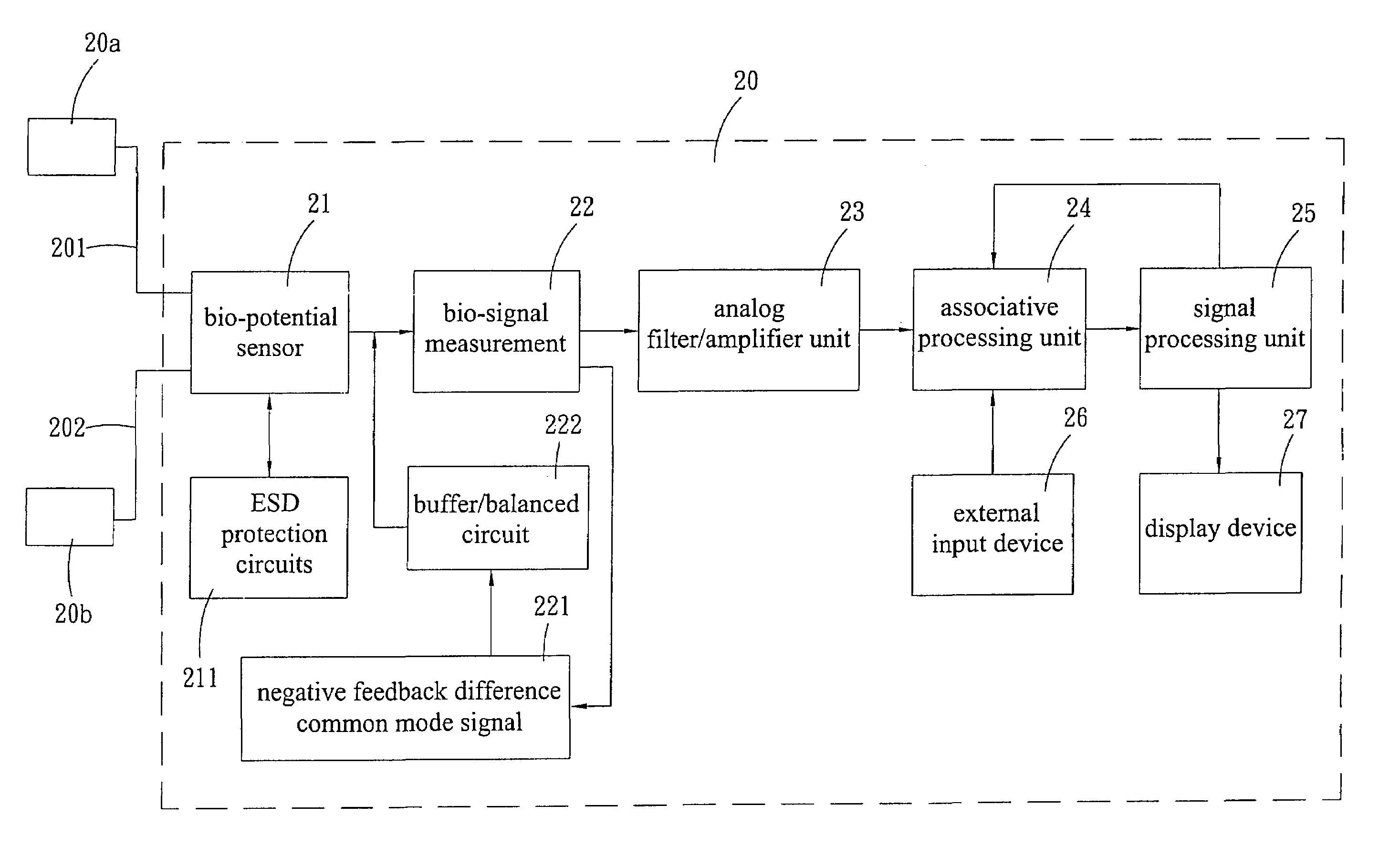
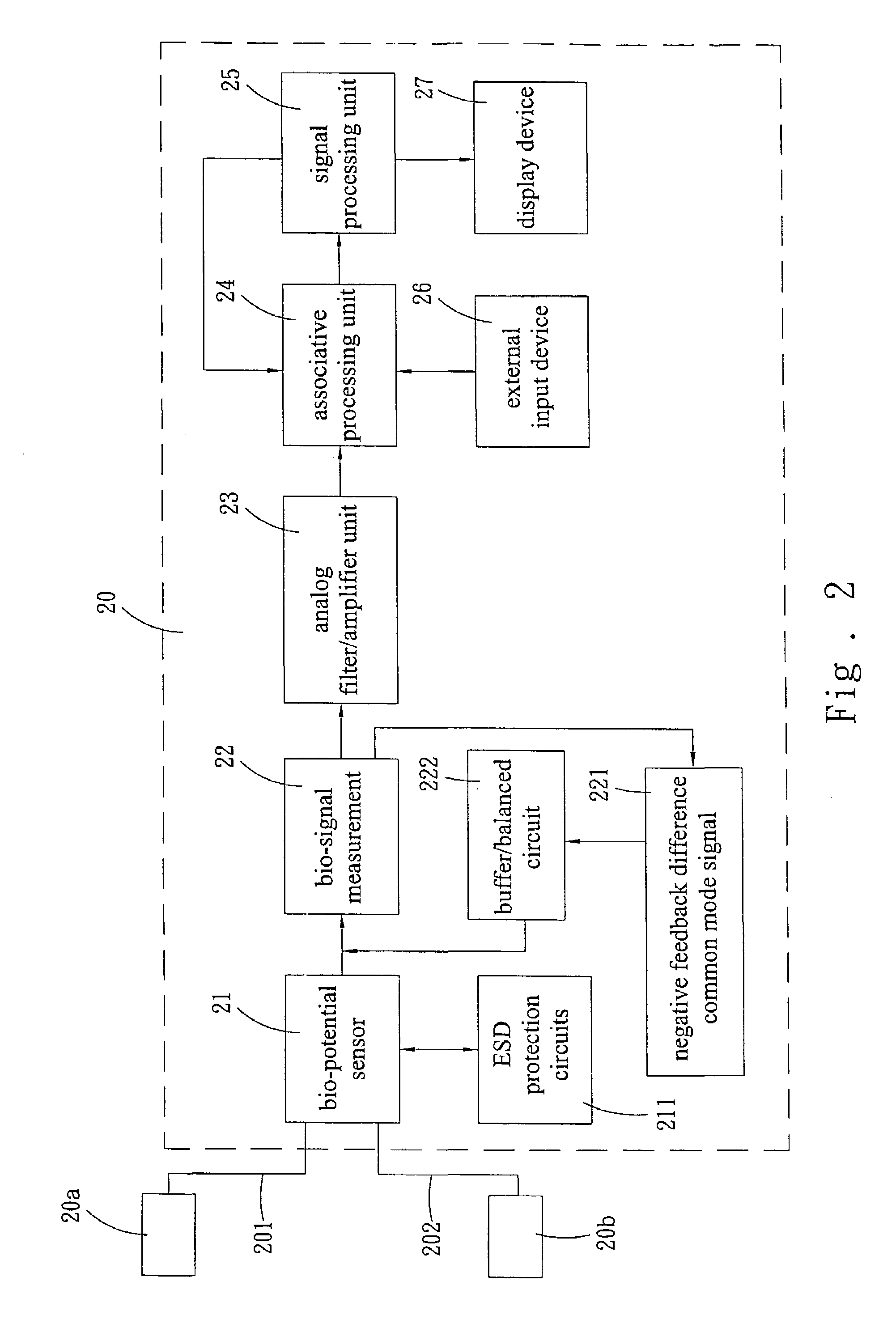
[0012]Please refer to FIG. 2 for the circuit block diagram of the present invention. In FIG. 2, a contact type pulse measurement device is a pulse measurement device installed to all kinds of handheld equipments, so that a user can grip the pulse measurement device to measure the pulse condition; wherein the contact pulse measurement device of the invention comprises a first active sensor electrode 20a and a second active sensor electrode 20b having opposite polarities with each other, and the two active sensor electrodes 20a, 20b are connected to a pulse measurement device 20 respectively by conductive wires 201, 202.

[0013]Unlike the prior art, the pulse measurement device 20 of the present invention comprises a bio-potential sensor 21 for connecting the foregoing two active sen...


PUM


Abstract

The present invention discloses a contact type of pulse measurement device, which comprises a first active sensor electrode and a second active sensor electrode having corresponding opposite polarities with each other; and the two active sensor electrodes respectively connected to the pulse measurement device by conductive wires and the pulse measurement device comprises a negative feedback difference common mode signal and a buffer / balanced circuit for providing a circuit with a self common point electrode potential. Therefore, the first bio-potential signal can be detected by means of the first active sensor electrode and the common point electrode. Similarly, a second bio-potential signal having the same magnitude but a different phase as the first bio-potential signal can be detected by the second active sensor electrode and the common point electrode.

Description

FIELD OF THE INVENTION[0001]The present invention relates to a contact type pulse measurement device, more particularly to a contact type pulse measurement device installed in handheld equipment for measuring the pulse of a user when the user holds such device by a hand.BACKGROUND OF THE INVENTION[0002]At present, there are two general methods used for measuring the heartbeat rate of exercisers when using sport equipments for the exercise. One method detects the change of blood density in the human skin for the pulse measurement, and the other method detects the potential signal produced by the weak amplitude of vibration of the current, which is the so-called bio-potential signal for the pulse measurement. For the method using the change of blood density in the exerciser's skin for the pulse measurement, a device such as a clamp or a bracelet is generally used to be fixed onto the exerciser's body. However, the device using a clamp or a bracelet is movable and thus the electric wir...

Claims


Application Information

Patent Timeline
Patent Type & Authority Patents(United States)
IPC IPC(8): A61B5/02A61B5/024A61B5/0245A63B22/02A63B69/16
CPCA61B5/02444A61B5/0245A61B5/6887A61H2230/06A63B22/02A63B69/16
Inventor CHIANG, CHENG-TANG
Owner BOSON TECH
Learn More