
Filled article

a filling and body technology, applied in the field of filling articles, can solve the problems of poor productivity, uneven surface of such inner bodies, and difficult covering of inner bodies with skin layers,

Inactive Publication Date: 2005-09-20
NAMBA PRESS WORKS CO LTD
View PDF26 Cites 2 Cited by
  • Summary
  • Abstract
  • Description
  • Claims
  • Application Information

AI Technical Summary

Problems solved by technology

However, a surface of such an inner body is not smooth, and a fraction of the inner body is easily separated from its surface even though the chips are firmly adhered to each other by the binder.
Thus, it is not easy to cover the inner body with the skin layer.
In addition, since the surface of the inner body is not smooth as described above, it takes a along time for covering the inner body with the skin layer, and this makes the productivity worse.
Also, even though such an inner body is covered with the skin layer, the skin layer is shifted relative to the inner body so that a wrinkle is produced on the surface of the skin layer and a seam of the skin layer is undesirably curved, and thus, as another problem, this makes its quality worse.
However, since a surface to be treated is inside the skin layer, such a treatment is difficult to carry out.
The surface-smoothness and the separation of a fraction of the inner body both become considerably worse, as the filler such as chips used for the inner body is harder.
Even though it is considered to recycle such waste, it is difficult to use the waste as filler used for the inner body due to the reasons described above.

Method used


Image

  • Filled article
  • Filled article
  • Filled article

Examples


example 1

[0041]FIGS. 4–7 show a method according to the present invention for manufacturing a headrest attached to a seat equipped in an automobile.

[0042]FIG. 4a is a front view of a skin layer of the headrest and FIG. 4b is its bottom view. The skin layer 40 of the headrest H used herein is porous and is made of a fiber material, and a soft slab formed urethane 41 is attached on its back surface. On the bottom of the skin layer 40, holes 42, 42 are provided for inserting a stay 44 therein. Also, a slit 43 as an opening for supplying filler therein is provided on the bottom of the skin layer 40. This slit 43 is usually closed as shown in FIG. 4c.

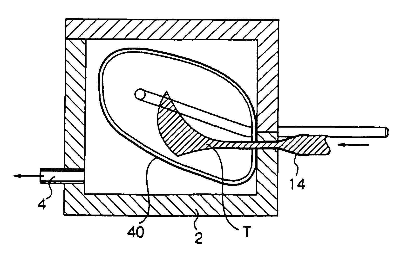
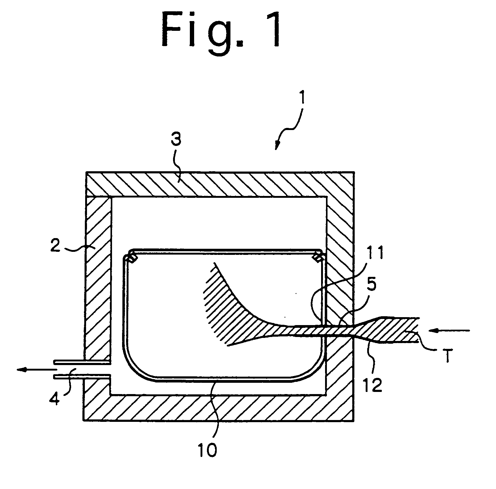
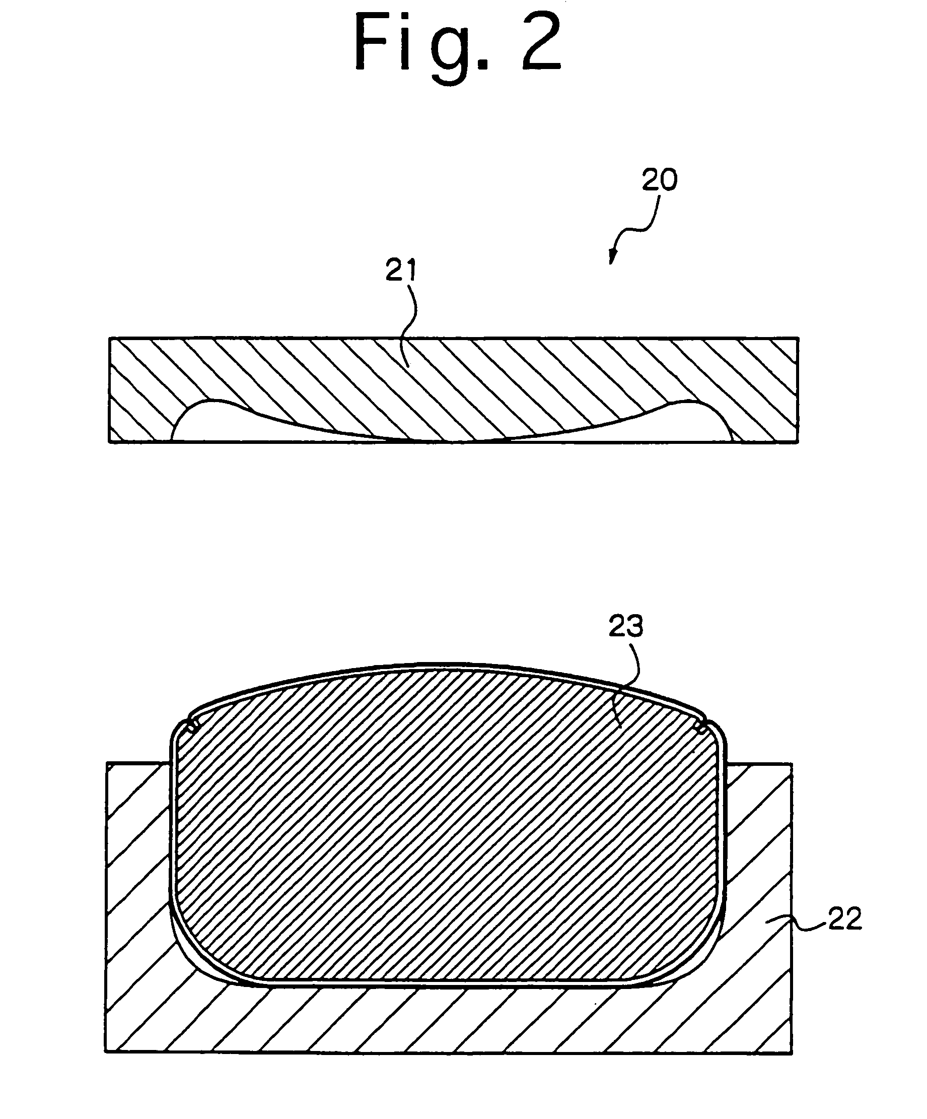
[0043]The stay 44 is inserted in the skin layer 40, and the skin layer 40 is then set in the main part 2 of the padding container 1 such that the slit 43 fits to the supply port 5, as shown in FIG. 5. Then, the main part 2 is closed by the lid part 3, and the funnel 14 is positioned so as to pass through between the slit 43 and the supply port 5 (FI...

example 2

[0051]In Example 1 described above, two separated devices such as the suction container and the molding container are used to mold the padded body. In Example 2, such a padded body is manufactured by use of only one device. Example 2 is now described with referring to FIGS. 8–11.

[0052]With reference to FIG. 8, a padding and molding container 80 has an upper mold 81 and a lower mold 82. The upper mold 81 is pivotally connected to the lower mold 82, and a cavity can be formed in the padding and molding container 80. The upper mold 81 has a slide block 81a and a suction port 84 connected to a vacuum pump. A supply port 85 is provided in the padding and molding container 80. The supply port 85 is provided at a position where the upper mold 81 meets the lower mold 82 such that the opening 43 of the skin layer 40 can fit to the supply port 85. Also, holes or channels (not shown) may be provided for position a stay.

[0053]While the padding and molding container 80 is closed by pivotally mov...

example 3

[0057]FIG. 12 shows a method according to the present invention for forming a padded body using a padding container 120 comprising a suction container 121 and a pre-molding container 122 provided therein. The pre-molding container 122 has an upper part 122a and a lower part 122b. The pre-molding container 122 has a cavity slightly larger than a finished product. The lower part 122b is fixed in the suction container 121. The suction container 121 has a suction port 121a connected to a vacuum pump (not shown) and a supply port 121b.

[0058]The pre-molding container 122 has an entry 123 to be fitted to the slit 43 of the skin layer 40 and through holes 124, 124 connected between the inside of the pre-molding container and the inner space of the suction container 121. While the suction container 121 is evacuated, the cavity of the pre-molding container 122 is also evacuated through the through holes 124, 124. Thus, since those through holes 124, 124 determine a flow direction inside the ...


PUM

PropertyMeasurementUnit
wt %aaaaaaaaaa
shapeaaaaaaaaaa
surface-smoothnessaaaaaaaaaa

Abstract

A method for manufacturing a padded body composed of a skin layer formed in a bag shape and filler made of a granular or fragmental material padded into the skin layer comprising the steps of: mixing the filler and a water reactive binder; padding a mixture of the filler and the binder into the skin layer to form a padded body; and passing steam through the padded body. The binder reacts to the steam so that the filler adheres each other and adheres to an inner surface of the skin layer.

Description

[0001]This application is a 371 of PCT / JP00 / 00908 filed on Feb. 17, 2000.TECHNICAL FIELD[0002]The present invention relates to a padded body molding technique and, in particular, relates to a padded body composed of a skin layer formed in a bag shape and filler such as chips padded into the skin layer, a method for manufacturing such a padded body and padding and / or molding devices used for the manufacture thereof.BACKGROUND OF THE ART[0003]A cushion may be used for a headrest and an armrest equipped in an automobile. Such a cushion is composed of a skin layer formed in a bag shape and an inner body molded in a desired three-dimensional shape, and the inner body is inserted in and covered with the skin layer. The inner body is formed of filler such as urethane chips, and such an inner body can be obtained by passing steam through a mixture of urethane chips and a water reactive urethane binder to adhere those chips to each other.[0004]However, a surface of such an inner body is not ...

Claims


Application Information

Patent Timeline
Patent Type & Authority Patents(United States)
IPC IPC(8): B29C39/10B29C44/02B29C44/14B29C67/20B60N2/46B60N2/48C08J9/00C08J9/33B29C33/04B29C31/04B29C33/10B29C35/04B29C33/20B68G7/06B29K103/00B29L31/58B60N2/75
CPCB29C39/10B29C44/14B29C67/20B60N2/46B60N2/48C08J9/33B29C31/041C08J2475/04B29C33/10B29C33/20B29C35/049B29K2075/00B29K2105/16B29K2503/00B29L2031/3023C08J2375/04C08J2205/06B29C33/04B60N2/75B60N2/80
Inventor OGAWA, TAROSENOO, YASUMASATODA, YASUYUKIKATAYAMA, MITSUOHARA, TAKAHIRO
Owner NAMBA PRESS WORKS CO LTD
Learn More