
Template for preparing a wire harness

Inactive Publication Date: 2005-09-20
MARIS GEORGE P
View PDF16 Cites 15 Cited by
  • Summary
  • Abstract
  • Description
  • Claims
  • Application Information

AI Technical Summary

Benefits of technology

[0010]The template for preparing a wiring harness of the present invention addresses the aforementioned needs in the art. The template for preparing a wiring harness allows a customization shop to completely and accurately prepare a wiring harness for after-market installation of various electrical components into a vehicle. The template for preparing a wiring harness allows for quick and accurate measurement of each particular wiring run that makes up the overall harness without the need to resort to bulky manuals for measurement guidelines and with minimal possibility that a particular run short will be cut short. The present invention allows a customization shop to assemble the wiring harness per specifications and thereafter to encase the completed harness into a conduit for subsequent installation into the vehicle. The template for preparing a wiring harness allows for dynamic adjustment of the lengths of the runs in the event that the size of the vehicle changes or if a change of placement within the vehicle of some electric devices occurs.

Problems solved by technology

This is due to the fact that each particular end user has differing needs from similar end users and the custom installation of differing devices for a particular end user is very cost-prohibitive to a large vehicle manufacturer.
However, this method is time consuming as each run has to overcome various hurdles, such as passing through the fire wall of the vehicle or being inserted into the roof pillar of the vehicle.
Additionally, having many individual runs of wires installed can create a messy and cluttered effect.
Additionally, the wiring harness leaves all of the wires so installed, compact and organized.
The problem with this method is that during the cutting process, mistakes in measurement with respect to the length of an individual wiring run can be made, or mistakes in measurement with respect to the turn out point from the main harness for a particular wiring run can be made.
As such mistakes may not be caught until late in the installation process and as many end users have requirements that all after-market wiring be contained within the conduit of the wiring harness, such mistakes can be time-consuming and costly.

Method used


Image

  • Template for preparing a wire harness
  • Template for preparing a wire harness
  • Template for preparing a wire harness

Examples


Embodiment Construction

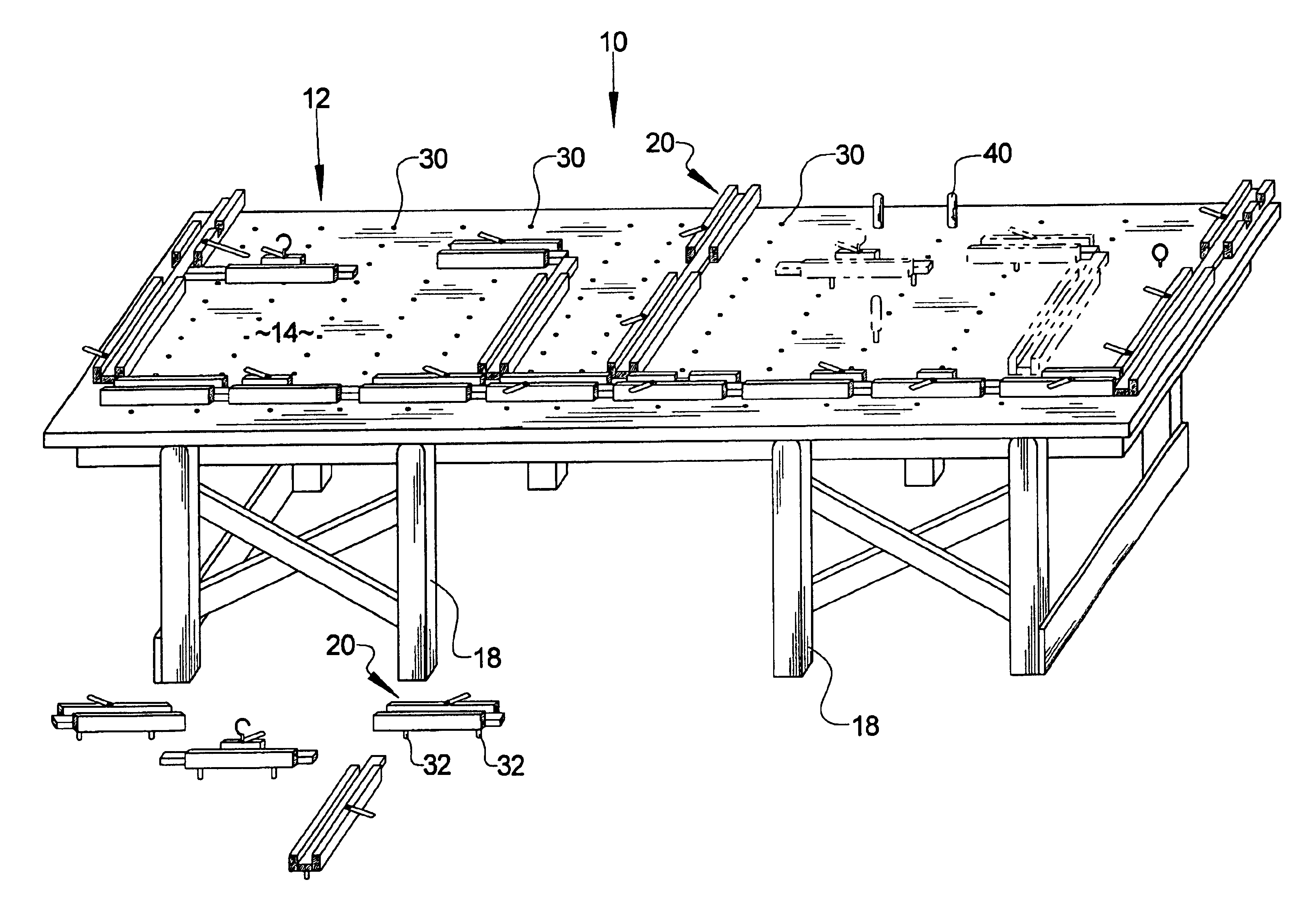
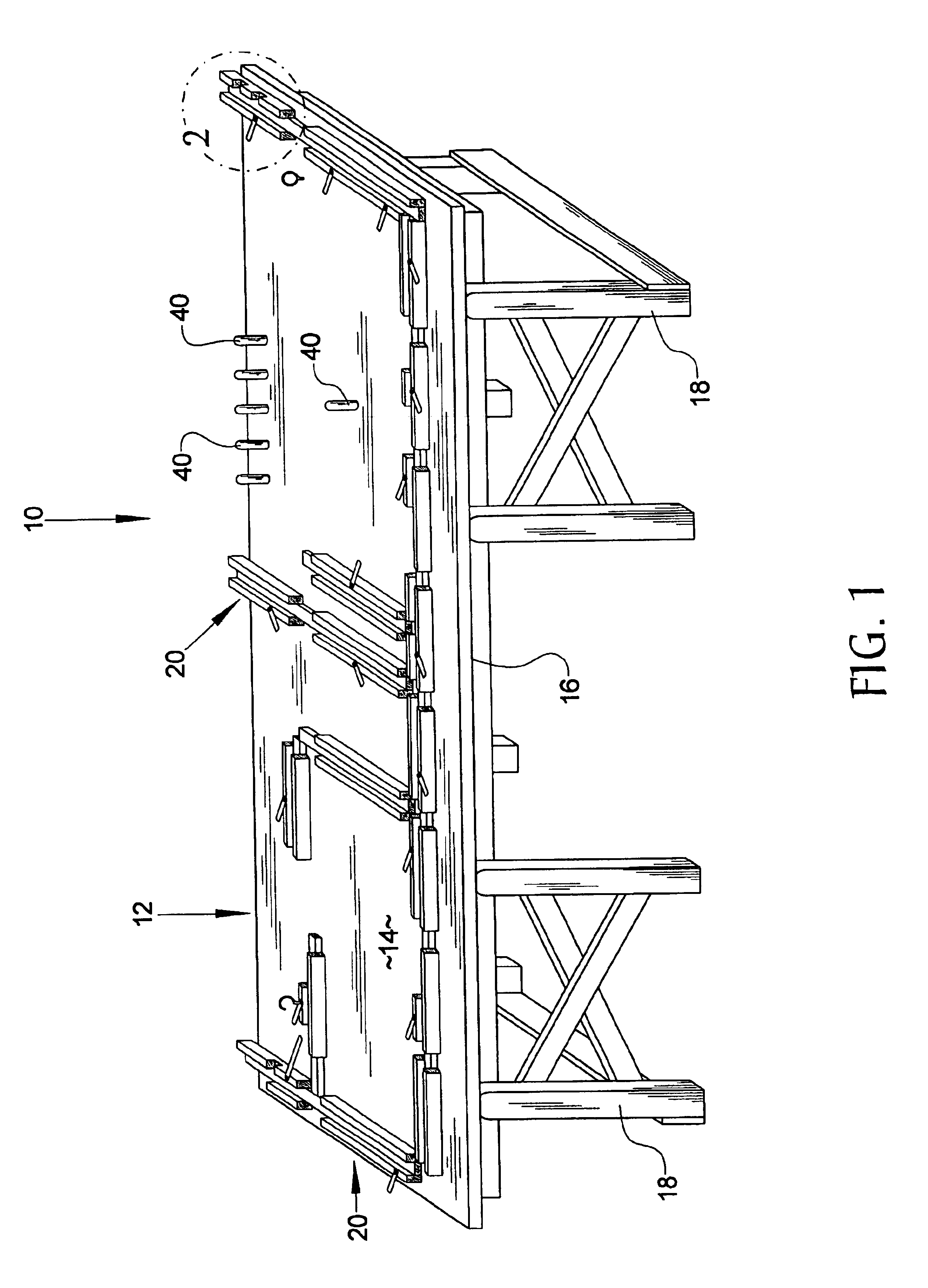
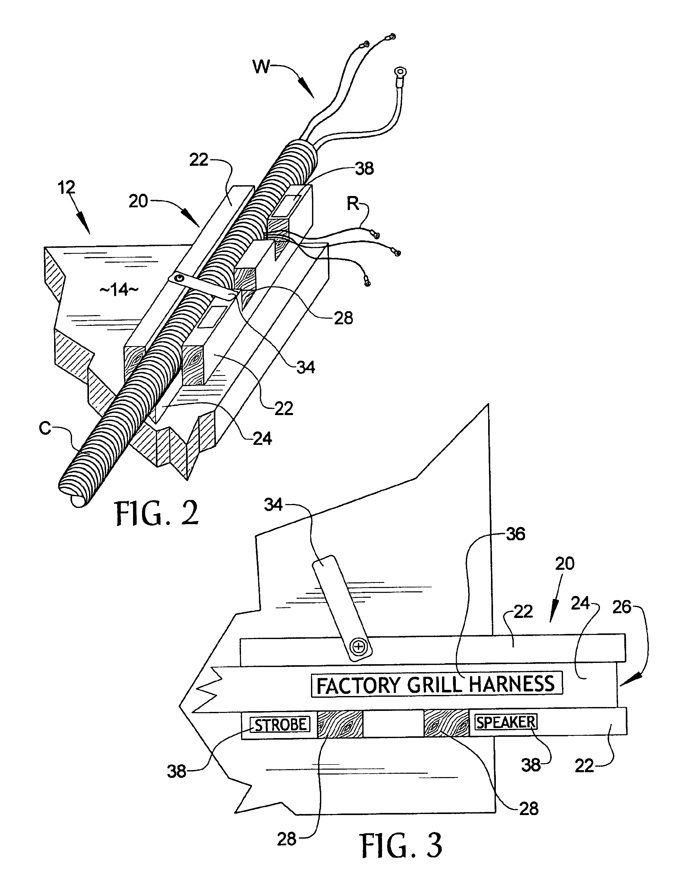
[0018]Referring now to the drawings, it is seen that the template for preparing a wiring harness, generally denoted by reference numeral 10, is comprised of a base member 12 having a generally flat top surface 14 and a bottom surface 16. The base member 12 may be laid upon an appropriate work surface such as a table or may be provided with its own legs 18 in order to allow the device 10 to be freestanding. A station 20 is provided and has a pair of flanges 22 joined by a floor 24 that form a channel 26. Some of the flanges 22 have a discontinuity 28 along each particular flange's length. Multiple similar stations 20 can be provided and each is attached to the top surface 14 of the base member 12. The attachment of each station 20 to the base member 12 may be removable and may be facilitated by a pegboard style attachment system, as best illustrated in FIG. 4, wherein the top surface 14 of the base member 12 is provided with a plurality of female openings 30 and each station 20 is pr...


PUM


Abstract

A template for preparing a wiring harness allows for quick and accurate preparation of the harness for subsequent installation within a vehicle. The template has a base member with one or more stations attached thereto, the stations having channels and some discontinuities located on the side walls that form the channels. The harness is assembled within the channels and individual wire runs protrude through a particular discontinuity.

Description

BACKGROUND OF THE INVENTION[0001]1. Field of the Invention[0002]The present invention relates to a template that is used to construct an after-market wiring harness for use in vehicles that have wiring needs beyond those provided by the manufacturer of the vehicle.[0003]2. Background of the Prior Art[0004]Many vehicles, such as police cars, the fire chief's car, tow trucks, and construction site trucks, have various devices installed onto the vehicle after the vehicle is built in standard fashion at the factory. Such after-market devices include computer terminals, various lights and light bars, sirens, communication radios, etc. Typically, the car is manufactured in standard fashion and delivered to the end user with these various after-market devices installed after the original vehicle manufacturing has occurred. This is due to the fact that each particular end user has differing needs from similar end users and the custom installation of differing devices for a particular end us...

Claims


Application Information

Patent Timeline
IPC IPC(8): H02G1/06H01R43/00H01B13/012H01R43/28
CPCH01B13/01227H01R43/28H02G3/00Y10T29/5187Y10T29/53243Y10T29/49162Y10T29/49117Y10S269/903
Inventor MARIS, GEORGE P.
Owner MARIS GEORGE P
Learn More