Method of fabricating multipole lens, multipole lens, and charged-particle beam instrument equipped therewith

Active Publication Date: 2005-09-20
JOEL LTD
View PDF8 Cites 6 Cited by
  • Summary
  • Abstract
  • Description
  • Claims
  • Application Information

AI Technical Summary

Benefits of technology

[0012]It is an object of the present invention to provide a

Problems solved by technology

In this way, labor is required.
Hence, t

Method used


Image

  • Method of fabricating multipole lens, multipole lens, and charged-particle beam instrument equipped therewith
  • Method of fabricating multipole lens, multipole lens, and charged-particle beam instrument equipped therewith
  • Method of fabricating multipole lens, multipole lens, and charged-particle beam instrument equipped therewith

Examples


Embodiment Construction

[0026]The preferred embodiments of the present invention are hereinafter described in detail with reference to the drawings.

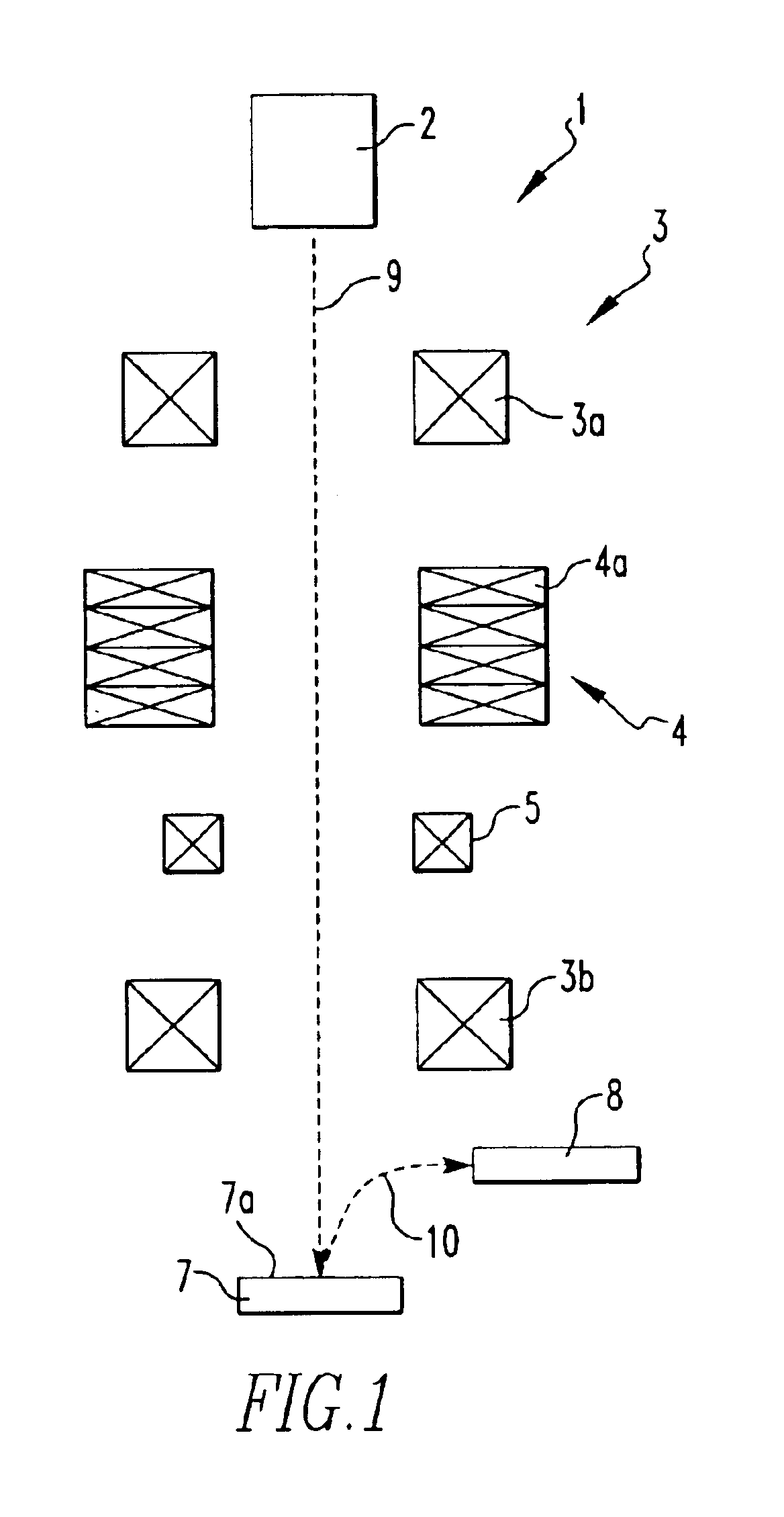
[0027]FIG. 1 is a schematic diagram showing a charged-particle beam instrument fitted with multipole lenses according to the present invention. In the present embodiment, a scanning electron microscope is used as an example of a charged-particle beam instrument. The scanning electron microscope, indicated by numeral 1, has an electron gun 2 acting as a source of a beam of charged particles, condenser lenses 3a, an aberration corrector 4, scan coils 5, an objective lens 3b, and a detector 8.

[0028]In this scanning electron microscope 1, an electron beam (charged-particle beam) 9 emitted and accelerated from the electron gun 2 is controlled by an illumination lens system 3 and sharply focused onto an observed surface 7a of a specimen 7. The illumination lens system 3 is composed of the condenser lenses 3a and the objective lens 3b. At this time, the electron beam ...


PUM


Abstract

A method of efficiently fabricating a multipole lens. The multipole lens has plural polar elements and an annular holding member. Each polar element has a held portion. The annular holding member is provided with through-holes for holding the held portions of the polar elements. A resin is injected into the through-holes in the holding member via openings formed in the holding member, the openings being in communication with the through-holes. The injected resin is cured, thus holding the held portions of the polar elements to the holding member within the through-holes.

Description

BACKGROUND OF THE INVENTION[0001]1. Field of the Invention[0002]The present invention relates to a method of fabricating a multipole lens having multipole elements, such as octopoles or dodecapoles and also to the multipole lens. Furthermore, the present invention relates to a charged-particle beam instrument fitted with such multipole lenses.[0003]2. Description of Related Art[0004]In a charged-particle beam instrument such as a scanning electron microscope, aberration in the electron beam that is a charged-particle beam is corrected when the beam is directed at a specimen, in order to appropriately image the specimen. A multipole lens is mounted as an aberration corrector within this charged-particle beam instrument to correct the aberration in the beam.[0005]A known construction of this multipole lens as shown in Japanese Patent Laid-Open No. H2-230647 has plural (e.g., 8 or 12) multipole elements which are supported by an annular holding member and a yoke disposed outside the ho...

Claims


Application Information

Patent Timeline
IPC IPC(8): H01J37/10H01J37/141H01J9/14H01J9/236H01J3/22
CPCH01J9/236H01J37/141Y10S430/143
Inventor KAWAI, EIJI
Owner JOEL LTD
Why Eureka
Try Eureka