Reflective liquid crystal display device and method for manufacturing the same

Inactive Publication Date: 2005-09-20
LG DISPLAY CO LTD
View PDF6 Cites 8 Cited by
  • Summary
  • Abstract
  • Description
  • Claims
  • Application Information

AI Technical Summary

Benefits of technology

[0013]An advantage of the present invention is to provide a reflective liquid crystal display device and a method for manufacturing the same, in which a reflective electrode is made of silver (Ag) which has higher reflectivity and higher heat-resistance than aluminum, so that it is possible to prevent the reflective electrode from deforming, thereby forming the reflective liquid crystal display device having high luminance.

Problems solved by technology

The transmissive liquid crystal display device has limitations in that it is hard to obtain ultra-thinness and lightness due to the weight and volume of the backlight.
Also, power consumption increases since the backlight is driven.
The reflective electrode being made of aluminum (Al) may deform during a heat treatment process due to a poor heat-resistance of aluminum (Al).

Method used


Image

  • Reflective liquid crystal display device and method for manufacturing the same
  • Reflective liquid crystal display device and method for manufacturing the same
  • Reflective liquid crystal display device and method for manufacturing the same

Examples


Embodiment Construction

[0028]Reference will now be made in detail to an embodiment of the present invention, example of which is illustrated in the accompanying drawings. Wherever possible, the same reference numbers will be used throughout the drawings to refer to the same or like parts.

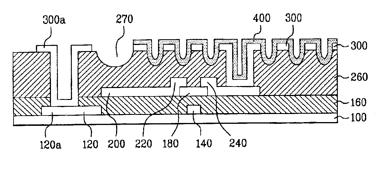
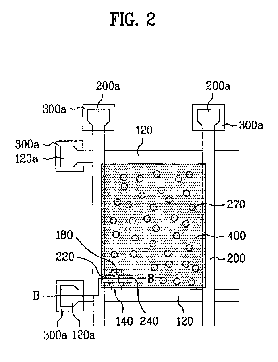
[0029]FIG. 2 is a plan view illustrating a reflective substrate of a reflective LCD device according to the present invention. FIG. 3A and FIG. 3B are sectional views illustrating a reflective substrate of a reflective LCD device according to the present invention taken along line B—B of FIG. 2. Although a unit pixel is shown in accompanying drawings, a plurality of pixels are formed in a matrix type at right and bottom sides in the context of the drawings.

[0030]As shown in FIG. 2 and FIG. 3A, a plurality of gate lines 120 are horizontally formed on a substrate 100, and a gate pad 120a is formed at each one end of the gate lines 120. A plurality of gate electrodes 140 are projected from the gate line 120. The gate line 12...


PUM


Abstract

A reflective liquid display device and a method for manufacturing the same which has high luminance. The reflective liquid crystal display device includes a plurality of gate and data lines formed on a reflective substrate to cross with one another, thereby defining a plurality of pixel regions; gate and data pads respectively formed at each one end of the gate and data lines; a thin film transistor connected to the gate and data lines; a passivation layer having a plurality of holes within the pixel region, being formed on an entire surface of the reflective substrate; a first transparent electrode formed on the passivation layer; a second transparent electrode formed on the passivation layer between the holes of the pixel region; and a silver (Ag) alloy layer formed on the second transparent electrode within the pixel region and the passivation layer having the holes.

Description

[0001]This application claims the benefit of the Korean Application No. P.2001-85288 filed on Dec. 26, 2001, which is hereby incorporated by reference for all purposes as if fully set forth herein.BACKGROUND OF THE INVENTION[0002]1. Field of the Invention[0003]The present invention relates to a liquid crystal display device, and more particularly, to a reflective liquid crystal display device having high reflectivity and a method for manufacturing the same.[0004]2. Discussion of the Related Art[0005]A typical liquid crystal display (LCD) device is provided with lower and upper substrates facing each other at a predetermined distance, and a liquid crystal layer formed between the lower and upper substrates. The liquid crystal layer is driven by an electric field formed between the lower and upper substrates, so that the light transmittance is controlled, thereby displaying an image on an LCD panel. However, the LCD device does not emit light by itself, so that a backlight is addition...

Claims


Application Information

Patent Timeline
IPC IPC(8): G02F1/1335G02F1/13G02F1/1343G02F1/1362
CPCG02F1/133553G02F1/13439G02F1/136227G02F1/1343
Inventor CHAE, GEE SUNG
Owner LG DISPLAY CO LTD
Why Eureka
Try Eureka