Inrush current control method using a dual current limit power switch

a power switch and inrush current technology, applied in the field of electronic systems, can solve the problems of increasing inrush current, limiting fixed turn on time, and not solving problems, and achieve the effect of regulating current flow

Inactive Publication Date: 2005-09-20
TEXAS INSTR INC
View PDF8 Cites 43 Cited by
  • Summary
  • Abstract
  • Description
  • Claims
  • Application Information

AI Technical Summary

Benefits of technology

[0008]A current limit circuit regulates the current flow through a power switch by measuring the current through the switch and comparing it to a reference voltage that represents the limit current. When the current through the power switch is greater than the limit current, the current in the power switch is pulled lower by a driver circuit which controls the power switch. By using a current limit reference voltage that has two levels, the power switch has two current limit thresholds. Using a comparator to compare the input voltage of the power switch to the output voltage of the power switch, an output signal is generated to control the current limit threshold. When the input voltage and output voltage has a large differential voltage, a lower current limit threshold voltage is selected. When the input voltage and output voltage has a small differential voltage, an upper limit threshold voltage is selected.

Problems solved by technology

This method is useful in most applications but does not solve the problem when very large input capacitors are used because the current through the power switch increases until the current limit is invoked between 0.7 A and 1 A which exceeds the 44 ohms specification required for USB peripherals.
Adding large capacitors to a distributed power system increases the inrush currents when powering up.
This fixed turn on time is a limitation for applications that have specifications for maximum allowable inrush currents and have requirements for wide variations of bulk capacitance, such as the Universal Serial Bus (USB).

Method used


Image

  • Inrush current control method using a dual current limit power switch
  • Inrush current control method using a dual current limit power switch
  • Inrush current control method using a dual current limit power switch

Examples


Embodiment Construction

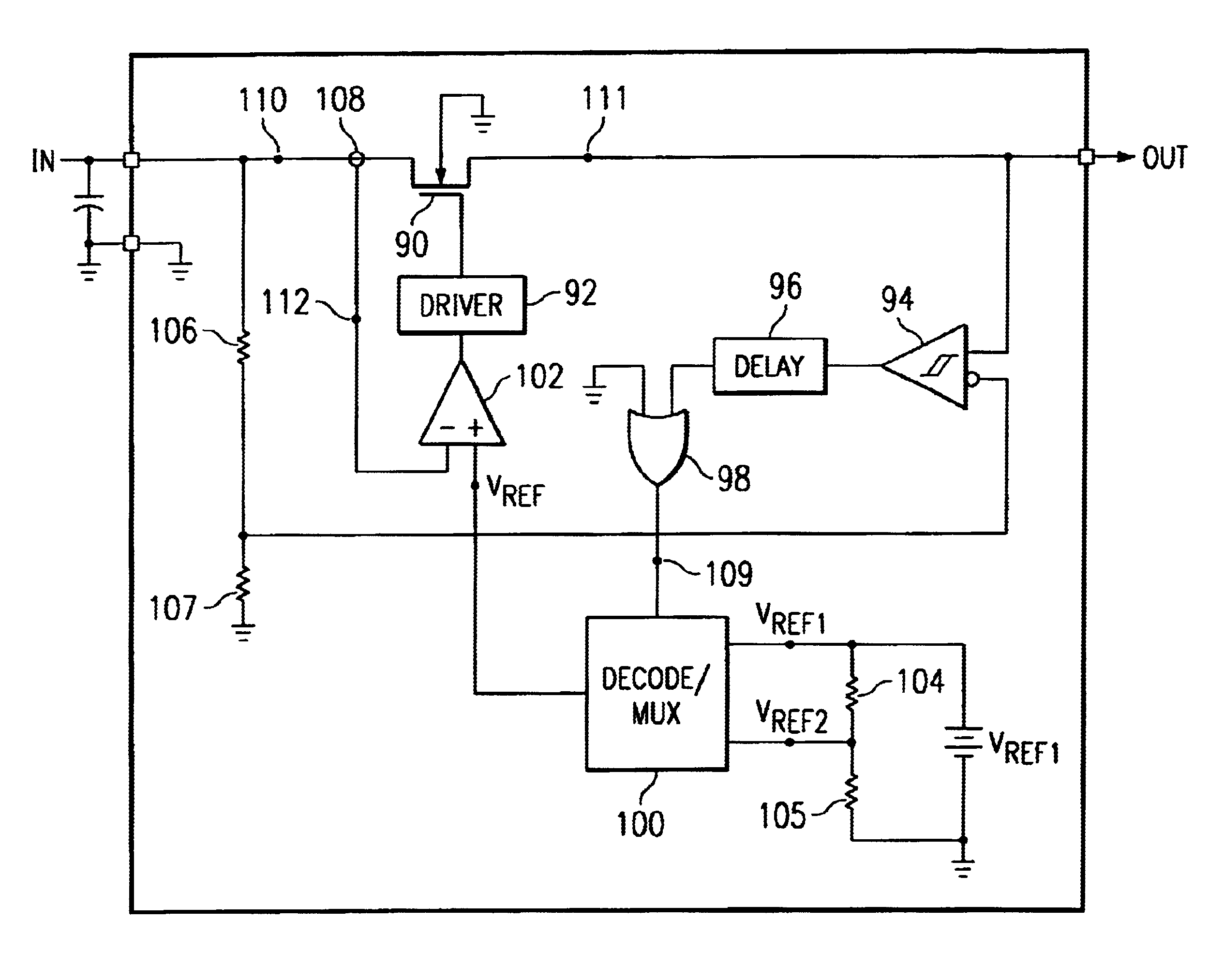
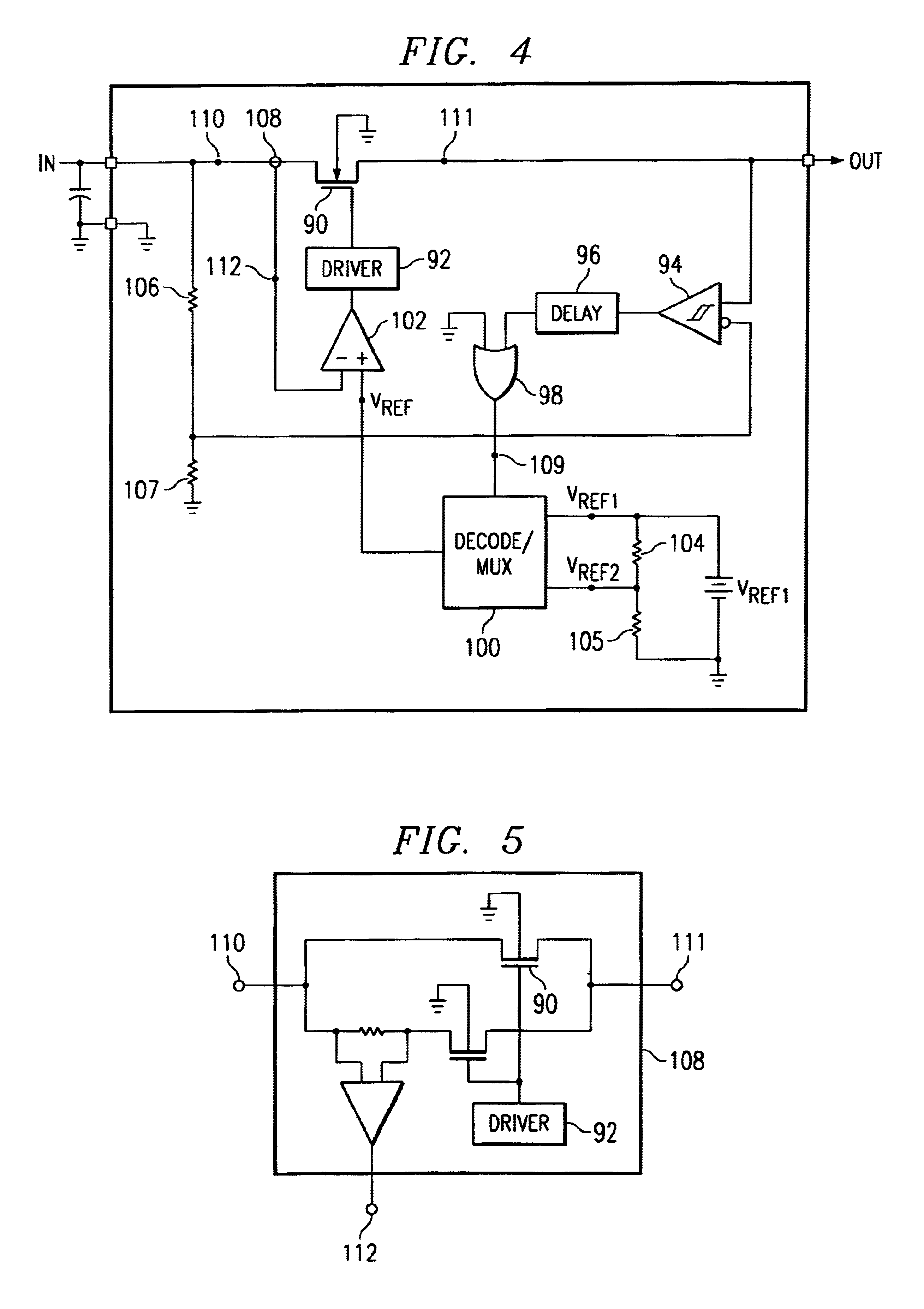
[0015]This invention solves the inrush current and maximum load requirements of the USB specification regardless of capacitance for USB peripherals by implementing a dual current limit in a power switch.

[0016]The preferred embodiment implements a dual, current-limited power switch. When the USB peripheral is initially connected to the USB system, the large bulk capacitance on the power switch output is at zero volts. The power switch is turned on slowly with the current limit set at the lower level of approximately 100 mA. The output capacitor voltage will slowly increase and the switch current will ramp until the 100 mA current limit. The switch will maintain the 100 mA current limit and output capacitor voltage will continue to increase, thus effectively limiting the capacitance load to resemble 44 ohms to the upstream USB power bus. When the output voltage reaches approximately 90% of the power switch input voltage, the switch will enable the upper current limit. Enabling the upp...


PUM


Abstract

A current limit circuit regulates the current flow through a power switch 90 by measuring the current through the switch 90 and comparing it to a reference voltage VREF that represents the limit current. When the current through the power switch 90 is greater than the limit current, the current in the power switch 90 is pulled lower by a driver circuit 92 which controls the power switch 90. By using a current limit reference voltage that has two levels, the power switch 90 has two current limit thresholds. Using a comparator 94 to compare the input voltage of the power switch 90 to the output voltage of the power switch 90, an output signal is generated to control the current limit threshold. When the input voltage and output voltage has a large differential voltage, a lower current limit threshold voltage is selected. When the input voltage and output voltage has a small differential voltage, an upper limit threshold voltage is selected.

Description

[0001]This application claims priority under 35 USC § 119 (e) (1) of provisional application No. 60 / 331,804 filed Nov. 20, 2001.FIELD OF THE INVENTION[0002]This invention generally relates to electronic systems and in particular it relates to an inrush current control method using a dual current limit power switch.BACKGROUND OF THE INVENTION[0003]Many USB peripherals need bulk capacitance on the input voltage supply rail greater than 10 uF but the USB 1.0, 1.1, and 2.0 specifications require that peripherals not exceed a load of 10 uF in parallel with 44 ohms. When bulk capacitance is needed in a peripheral, a power switch is utilized and turned on slowly usually 1 ms to 2 ms to minimize the inrush current. This method is useful in most applications but does not solve the problem when very large input capacitors are used because the current through the power switch increases until the current limit is invoked between 0.7 A and 1 A which exceeds the 44 ohms specification required for...

Claims


Application Information

Patent Timeline
Patent Type & Authority Patents(United States)
IPC IPC(8): H03K17/16H03K17/30H03K17/06
CPCH03K17/0822H02H9/001H03K17/302H03K17/166H03K17/063
Inventor DANIELS, DAVID G.ALHOUSSAMI, AIMANFOWLER, TOM L.
Owner TEXAS INSTR INC
Why Eureka
Try Eureka