
Parallel DC-to-AC power inverter system with current sharing technique and method thereof

a technology of power inverter and current sharing, which is applied in the direction of dc-ac conversion without reversal, process and machine control, instruments, etc., can solve the problems of product cost increase, system efficiency reduction, and volume increas

Inactive Publication Date: 2005-09-20
DELTA ELECTRONICS INC
View PDF3 Cites 70 Cited by
  • Summary
  • Abstract
  • Description
  • Claims
  • Application Information

AI Technical Summary

Benefits of technology

The present invention proposes a parallel DC-to-AC power inverter system with two DC-to-AC power inverters that use a current sharing technique to stabilize the output voltage. The system includes a controller module that detects the inductor current and load current, performs a numerical operation of the two current signals to generate an AC reference current signal, and generates the inverter control signals to stabilize the output voltage. The technical effect of this invention is to provide a more stable and efficient parallel DC-to-AC power inverter system without the use of parallel-linked inductor-capacitor filters.

Problems solved by technology

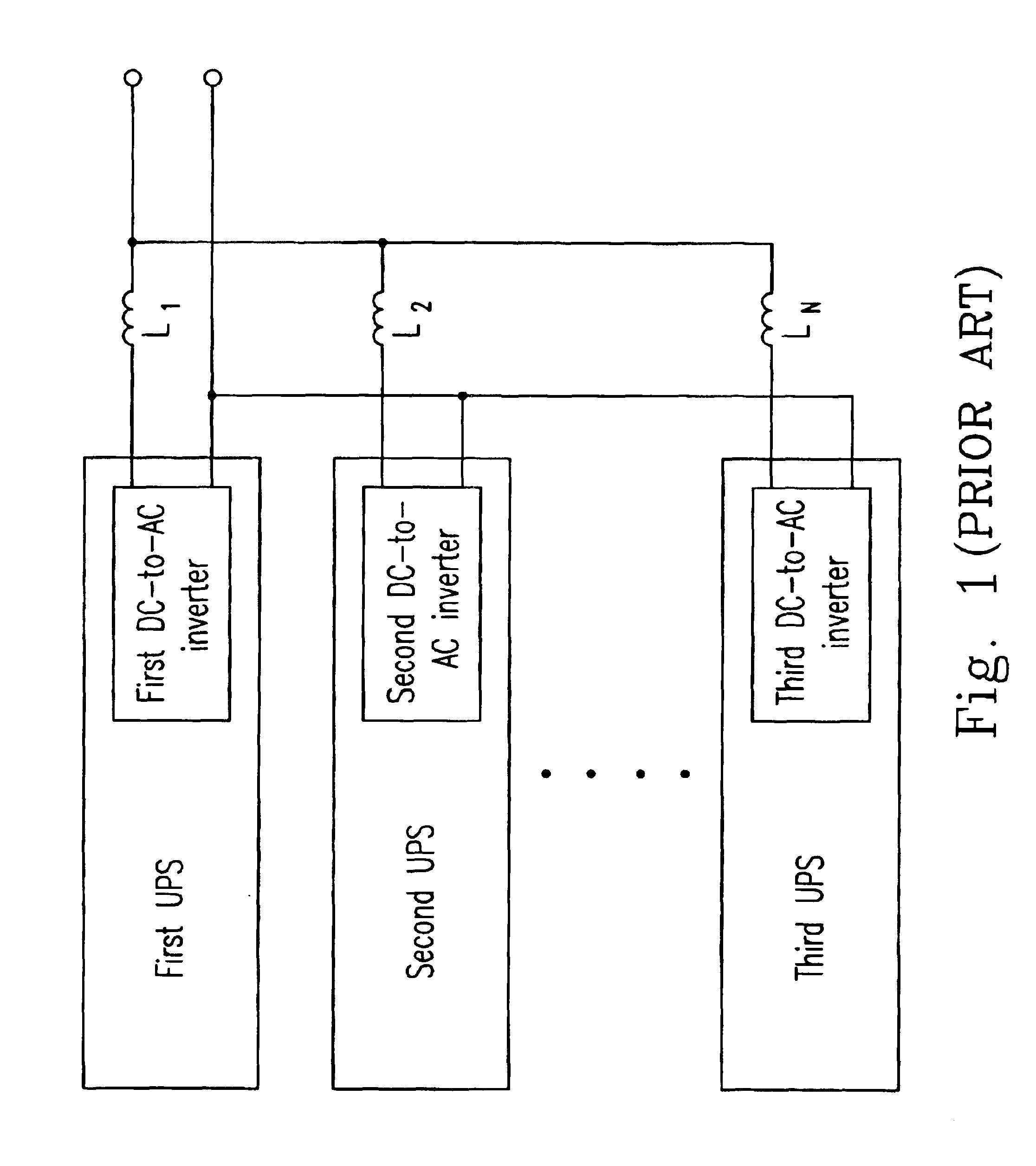
If each power supply were to operate independently, however, a disproportionate amount of the current required by the load would tend to be supplied by only one power supply while the other power supplies would supply significantly less current. FIG. 1 shows a parallel operation of an uninterruptible power supply system according to the prior art.
The technique has disadvantages in which the efficiency of the system is reduced, the volume of the system is increased, and the product cost is increased.

Method used


Image

  • Parallel DC-to-AC power inverter system with current sharing technique and method thereof
  • Parallel DC-to-AC power inverter system with current sharing technique and method thereof
  • Parallel DC-to-AC power inverter system with current sharing technique and method thereof

Examples


Embodiment Construction

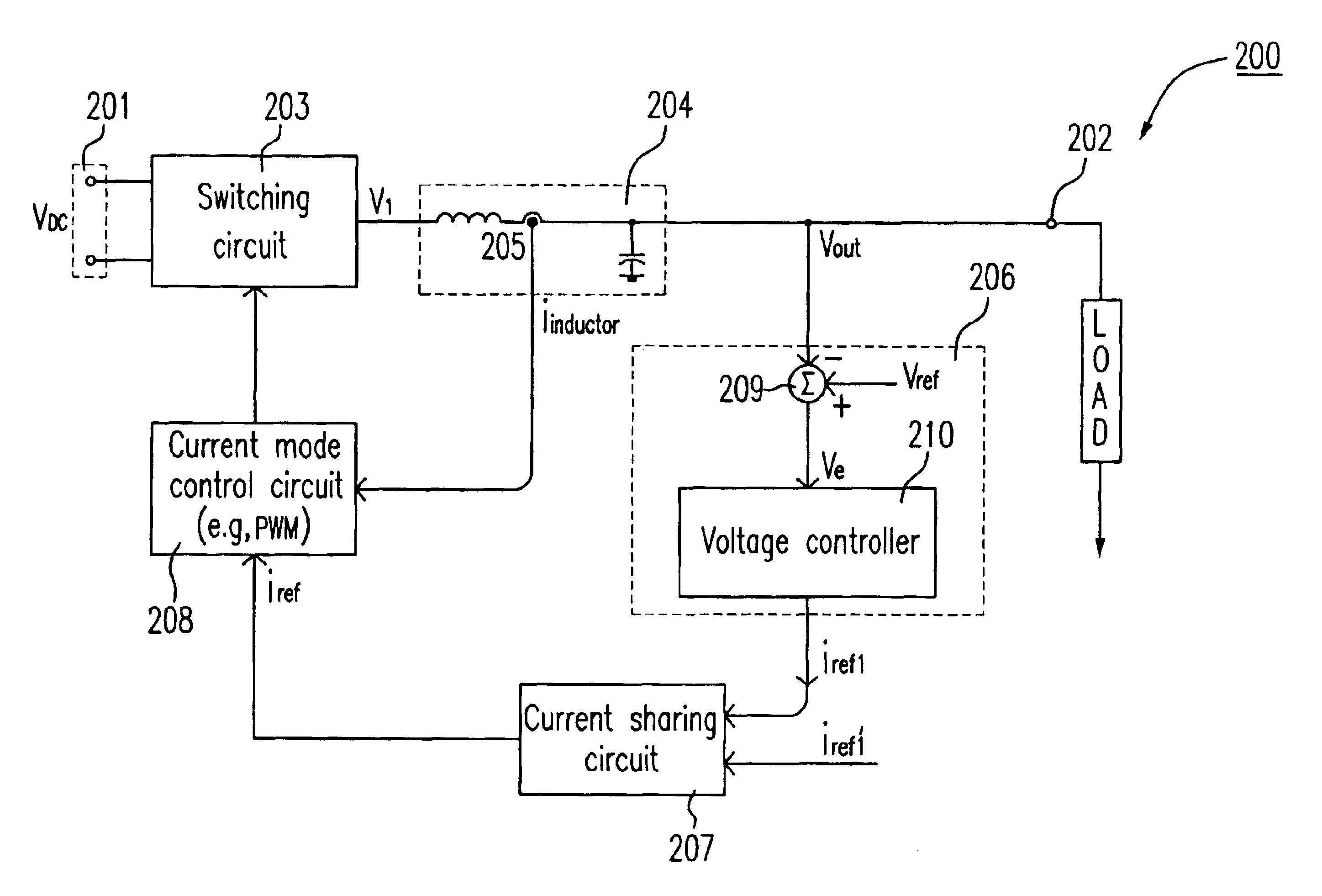
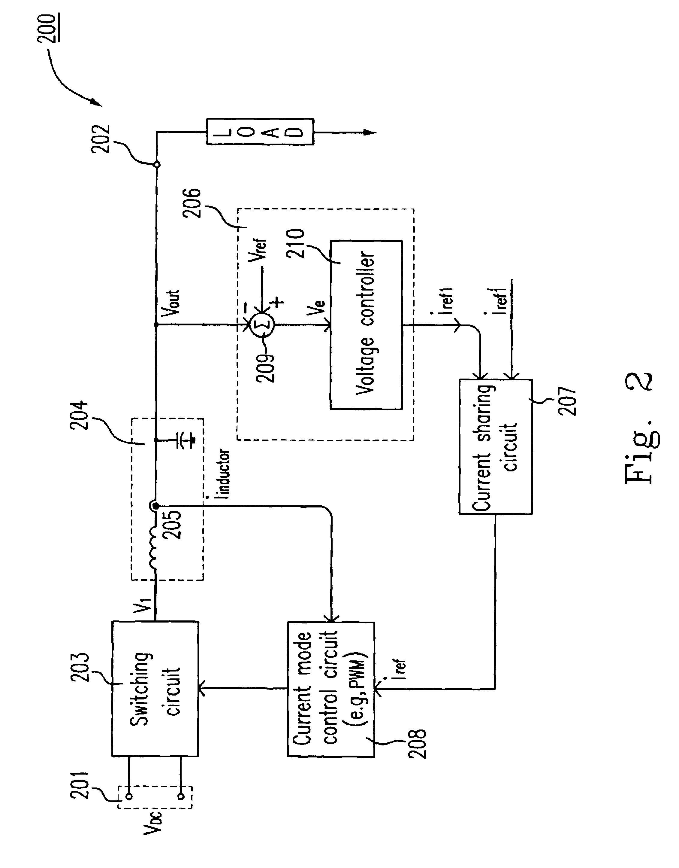
[0022]FIG. 2 illustrates a single DC-to-AC power inverter which utilizes a current sharing circuit according to a preferred embodiment of the present invention. As shown in FIG. 2, the DC-to-AC power inverter 200 includes an input port 201, an output port 202, a switching circuit 203, an inductor-capacitor filter 204, and a controller module. The switching circuit 203 is electrically connected between the input port 201 and the output port 202, which converts a DC voltage Vdc at the input port 201 to a first AC output voltage V1 responsive to inverter control signals. The inductor-capacitor filter 204 is electrically connected to the switching circuit 203 for filtering the first AC output voltage V1 to an AC output voltage at output port 202. And, the controller module includes a current sensor 205, a current control circuit 206, a current sharing circuit 207, and a current mode control circuit 208. The current sensor is electrically connected to the inductor-capacitor filter 204 fo...


PUM


Abstract

A parallel DC-to-AC power inverter system is provided. The parallel DC-to-AC power inverter system has a first DC-to-AC power inverter electrically connected in parallel with a second DC-to-AC power inverter, and each of the DC-to-AC power inverters includes an input port, an output port, a switching circuit electrically connected between the input port and the output port responsive to inverter control signals to convert a DC voltage at the input port to a first AC output voltage, an inductor-capacitor filter electrically connected to the switching circuit for filtering the first AC output voltage to an AC output voltage at output port, and a controller module for detecting an inductor current at the inductor-capacitor filter to generate an AC inductor current signal, for detecting the AC output voltage at the output terminals and transforming the AC output voltage to generate a first AC reference current signal, for detecting a load current at output port to generate an AC load current signal, for generating a second AC reference current signal by adding the first AC reference current signal to the AC load current signal, for performing a numerical operation of the second AC reference current signal of the first DC-to-AC power inverter and the second AC reference current signal of the second DC-to-AC power inverter to generate an AC reference current signal, and for generating the inverter control signals responsive to the AC reference current signal and the AC inductor current signal by sensing the inductor current at the inductor-capacitor filter. The related methods are also discussed.

Description

FIELD OF THE INVENTION[0001]The present invention relates to a parallel DC-to-AC power inverter system, and especially to a parallel DC-to-AC power inverter system with current sharing technique applied to an uninterruptible power supply system.BACKGROUND OF THE INVENTION[0002]Under certain circumstances, it can be desirable to provide a plurality of power supplies connected in parallel so as to have a common output node for supplying power to a load. If each power supply were to operate independently, however, a disproportionate amount of the current required by the load would tend to be supplied by only one power supply while the other power supplies would supply significantly less current. FIG. 1 shows a parallel operation of an uninterruptible power supply system according to the prior art. Please refer to FIG. 1. A typical parallel operation of an uninterruptible power supply (UPS) system must use a set of parallel-linking inductors L1, L2, . . . , Ln connected in parallel so a...

Claims


Application Information

Patent Timeline
Patent Type & Authority Patents(United States)
IPC IPC(8): H02M7/48H02M7/493
CPCH02M7/493
Inventor PAI, FU-SHENGLIN, HUNG-CHIEHLAI, YUAN-FUAN
Owner DELTA ELECTRONICS INC
Learn More