
Belt whose epsilonbreak/epsilonmax ratio is within a predetermined range and image forming apparatus having such belt

Active Publication Date: 2005-09-20
CANON KK
View PDF6 Cites 0 Cited by
  • Summary
  • Abstract
  • Description
  • Claims
  • Application Information

AI Technical Summary

Benefits of technology

[0020]An object of the present invention is to provide a belt capable of preventing image failure due to waving of the belt and rupture of the belt.

Problems solved by technology

However, in such an image forming apparatus, the transfer belt (endless belt) which is rotationally driven under tension may accompanied by the following two problems.
A first problem is that there is a possibility of the occurrence of image failure due to a permanent deformation of the transfer belt.
At the portions where such a waving is caused to occur, image failure is liable to occur.
This is attributable to the occurrence of irregularity in resistance at a transfer nip due to the waving.
When some gaps are formed in the thrust direction as described above, portions where the gaps are formed are supplied with an electric field smaller than that at other portions where the transfer nip is properly created, thus causing the resistance irregularity.
A second problem is that there is a possibility of rupture of the belt due to a tension which is locally applied.
However, it is difficult to uniformize the macroscopic tension applied to the belt in a plane where the belt is extended.
This is attributable to non-uniformity of the endless belt in terms of its material or a slight deviation of alignment of the belt-extension mechanism.
The non-uniformity of the belt material may, e.g., include a thickness irregularity of the belt, nonuniform dispersion of an electroconductive filler and non-uniformity in crystallization of a resin.
The thickness irregularity of the belt causes an unevenness of stress in the belt-extension mechanism, and the stress may locally exceed the tensile strength of the belt to cause permanent deformation, and at worst, rupture of the belt.
Further, the incorporation of the filler can be regarded as the presence of molecular-structure defects at spots where the filler is present, so that there is a possibility that the strength of the belt is locally lowered.
As a result, in a state in which the electroconductive filler is non-uniformly dispersed, there is a possibility that the rupture is liable to occur in spots where the filler is concentrated.
Further, progress of crystallization of the resin is locally caused to occur, so that the material possessing the non-uniformity exhibits energy elasticity at the spots where the crystallization progresses, thus lowering its elasticity compared with a high elasticity limit attributable to its original entropic elasticity.
As a result, there is the possibility of the occurrence of belt rupture.
Further, stress unevenness may occur also due to the alignment deviation of the beltextension mechanism.
As a result, an uneven torque due to friction between the rib and the rib guide is caused to occur, thus leading to an unevenness of tension in the belt-extension plane.
Even if the regulation by the rib guide is not performed, the alignment deviation cannot be negligible.
In such a case, it may be assumed that a large tension is applied diagonally to the belt in the belt-extension plane, thus leading to the unevenness of tension.
The unevenness of stress due to those factors generates locally a large stress.
If such a localized large stress exceeds the tensile rupture strength of the belt, there is a possibility of rupture of the belt.
Incidentally, Japanese Laid-Open Patent Application (JP-A) Hei 10-207243 and JP-A 11-167290 have proposed solutions to problems, such as distortion or deformation of an endless belt but have failed to provide sufficient belt performance.

Method used


Image

  • Belt whose epsilonbreak/epsilonmax ratio is within a predetermined range and image forming apparatus having such belt
  • Belt whose epsilonbreak/epsilonmax ratio is within a predetermined range and image forming apparatus having such belt
  • Belt whose epsilonbreak/epsilonmax ratio is within a predetermined range and image forming apparatus having such belt

Examples


embodiment 1

(Embodiment 1)

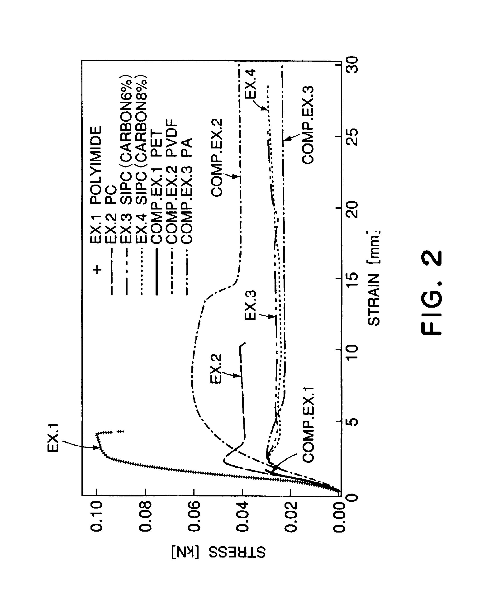
[0056]An endless belt was prepared by using polyimide as the base material and carbon black as the electroconductive filler contained in the base material in an amount of 20 wt. parts.

embodiment 2

(Embodiment 2)

[0057]An endless belt was prepared by using polycarbonate (PC) as the base material and carbon black as the electroconductive filler contained in the base material in an amount of 20 wt. parts.

embodiment 3

(Embodiment 3)

[0058]A seamless belt was prepared by using polycarbonate modified with Si (SiPC) as the base material and carbon black as the electroconductive filler contained in the base material. The carbon black was mixed in the SiPC in an amount of 6 wt. parts. The modification with Si was a treatment for improving dispersion property of the electroconductive filler.


PUM


Abstract

A belt extends a plurality of rollers, and bears thereon an image formed by an image forming device or a transfer material onto which the image is transferred. The belt satisfies the following relationship: 1.5≦εbreak / εmax≦10, wherein εmax represents the strain at the time of applying to the belt a maximum stress value obtained from a stress-strain curve measured in accordance with JIS K7161, and εbreak represents the strain at a breaking point of the belt.

Description

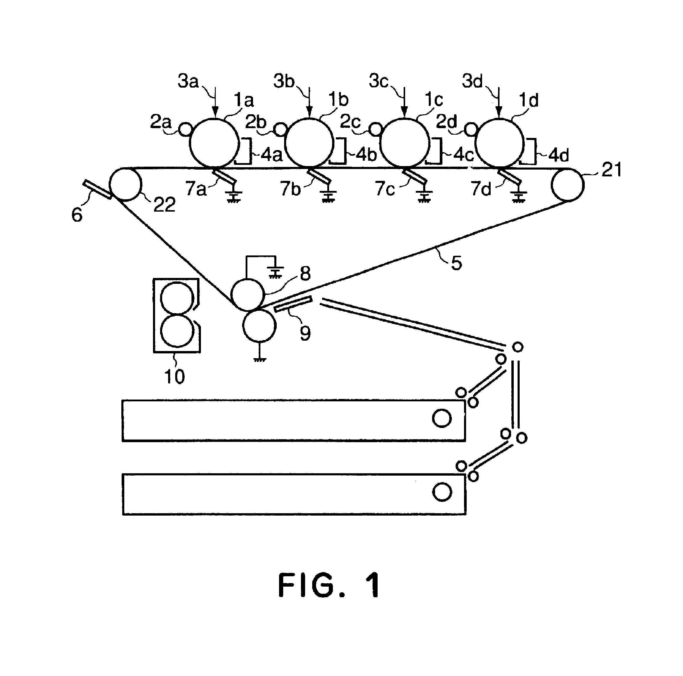
FIELD OF THE INVENTION AND RELATED ART[0001]The present invention relates to an intermediate transfer belt, for an image forming apparatus, which transfers an image onto a transfer material to provide an image or relates to a transfer material carrying belt.[0002]FIG. 5 is a schematic structural view showing an embodiment of a conventional tandem type full-color image forming apparatus (e.g., a full-color copying machine).[0003]Referring to FIG. 5, the image forming apparatus includes four photosensitive drums 100a, 100b, 100c and 100d which are respectively rotationally driven and uniformly charged by chargers 101a, 101b, 101c and 101d, respectively, and then are subjected to scanning exposure on the basis of image information by exposure apparatus 102a, 102b, 102c and 102d, respectively, to form thereon an electrostatic latent image, respectively.[0004]The respective electrostatic latent images are developed by developing devices 103a, 103b, 103c and 103d, respectively. The develo...

Claims


Application Information

Patent Timeline
IPC IPC(8): G03G15/16G03G15/00
CPCG03G15/1605G03G2215/0129G03G2215/0141G03G15/162
Inventor SAITO, MAKOTO
Owner CANON KK
Learn More