
Roof tile support

a technology for supporting roof tiles and roofs, which is applied in the direction of roofs, snow traps, building repairs, etc., can solve the problems of stepping on the middle of a tile, breaking tiles, and difficulty in walking on the floor without breaking tiles

Inactive Publication Date: 2005-09-27
SMITH GARY E
View PDF66 Cites 30 Cited by
  • Summary
  • Abstract
  • Description
  • Claims
  • Application Information

AI Technical Summary

Benefits of technology

"The present invention provides a roof tile support element that allows individuals to walk confidently on a tile roof without breaking tiles. The support element is compatible with a broad range of roof tiles and is adjustable during installation. The support element is wedge-shaped to provide support under as much of the tile as possible, distributing forces over the tile and through the support element to the roofing surface. The support element is independent of the roof tiles, making it more cost-effective. The roof tile support system increases the load capacities of the tiles and improves the walkability of the roof. The method for installing the support element involves placing a support element on a roofing surface, placing a roof tile over the support element, and securing the roof tile to the roofing surface."

Problems solved by technology

One of the only disadvantages of a tile roof is that it is difficult to walk on it without breaking tiles.
Careless foot placement or just “heavy feet” can result in broken tiles.
Stepping on the middle of a tile will likely break it because the tile is not well supported in that location.
There are several problems with this approach.
First, because the posts are an integral part of the tile and consist of the same brittle material as the tiles, they often break off during delivery, installation, or use.
Second, the tiles cannot be packaged as compactly and the volume that the tiles occupy during delivery is doubled, leading to increased shipping and delivery costs.
A third problem with the posts is that the amount of overlap, or head lap, for those tiles should not be adjusted.
In this condition, the post is not supporting the tile and the tile is likely to fracture when stepped on.
In this condition, the post is likely to snap off under a person's weight and the tile is just as likely to break as if there were no post at all.
The biggest problem with these tile structures is their lack of flexibility.
These pre-supported tile structures require precise alignment and cannot be easily modified by the installer to fit the shape of the roof.
Additionally these tile structures are sometimes expensive and are not available in as many colors and styles as the individual roof tiles.

Method used


Image

  • Roof tile support
  • Roof tile support
  • Roof tile support

Examples


Embodiment Construction

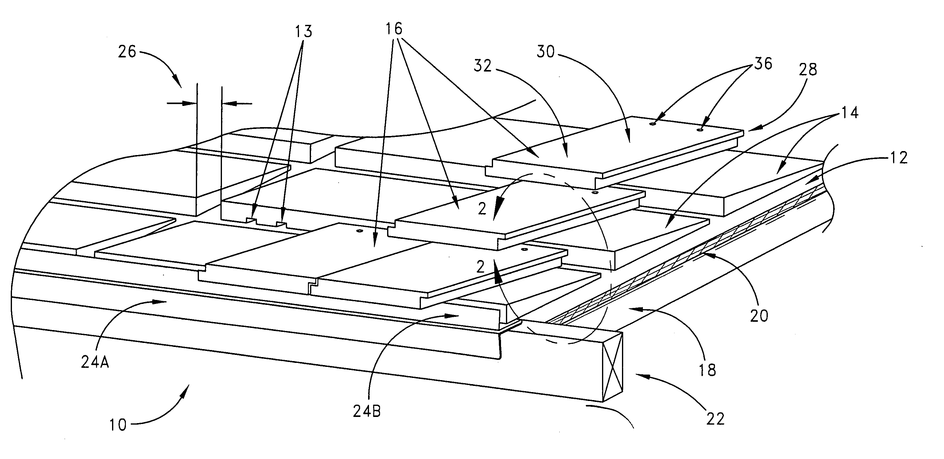
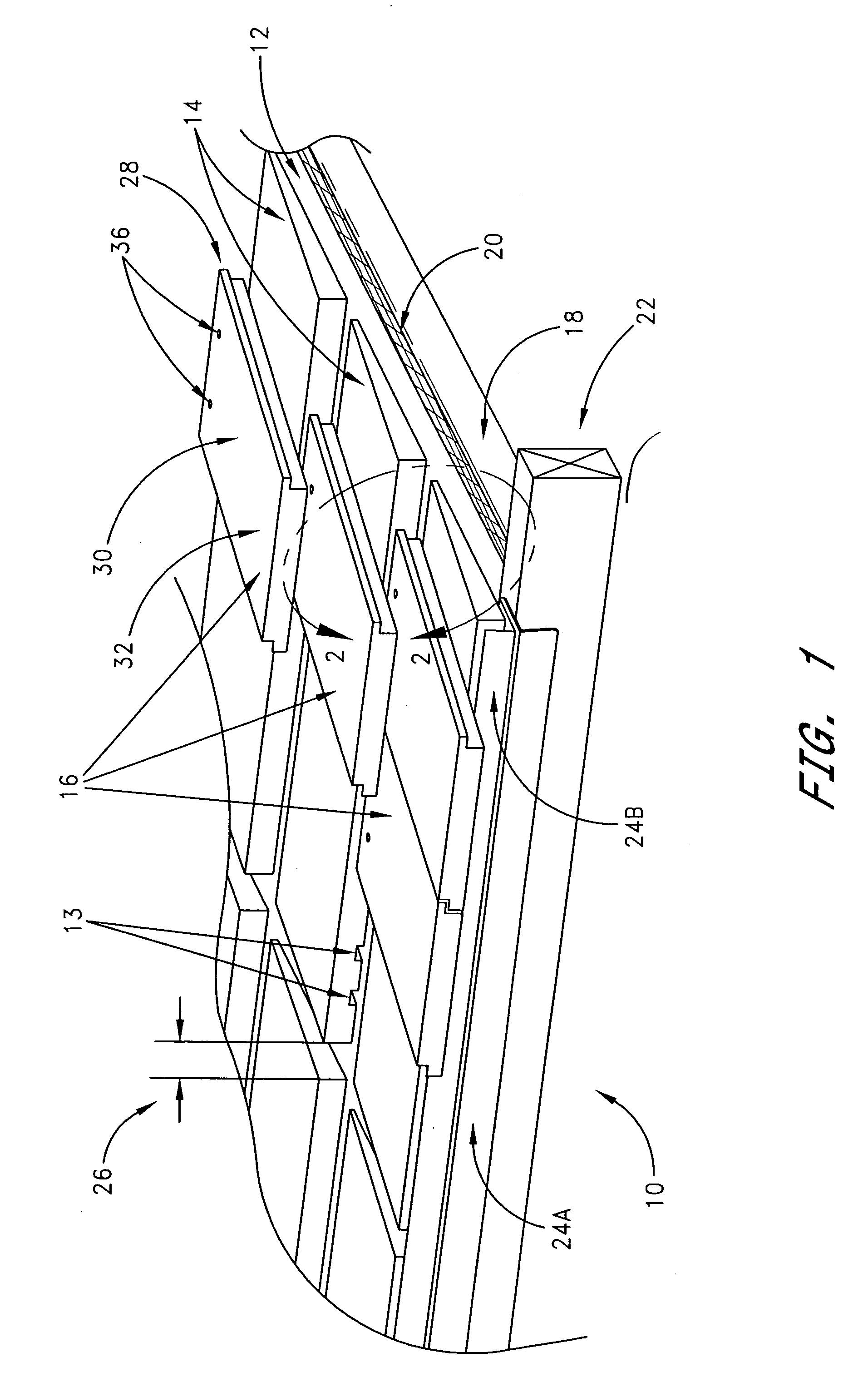
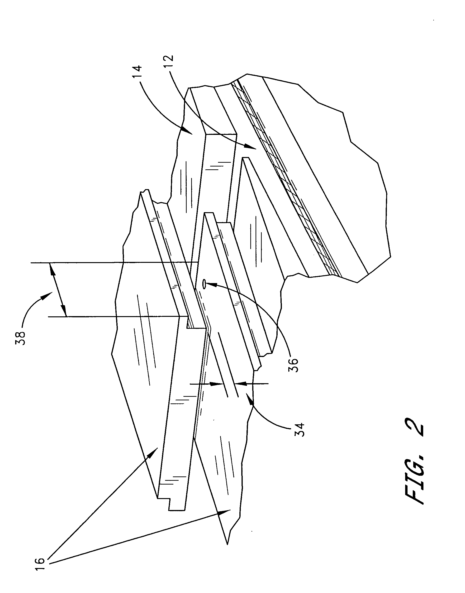
[0023]One embodiment of the invention is illustrated in FIG. 1, in which a roof tile support system 10 is shown covering a portion of a roof. A roofing surface 12 is shown. Several roof tile support elements 14 are shown resting on the roofing surface 12. Finally, several roof tiles 16 are shown resting on the roof tile support elements 14 and the roofing surface 12.

[0024]Preferably, the roofing surface 12 is a structure capable of receiving and supporting a tile roof. In a preferred embodiment of the invention, the roofing surface 12 is a supported plywood deck 18 covered by tarpaper 20. In other embodiments of the invention, the roofing surface 12 also includes battens to which roof tiles 16 are attached. In the preferred embodiment of FIG. 1, one end of the roofing surface 12 has a wooden cross member 22 to which the eave metal 24a,b of the roof is attached. One skilled in the art will be familiar with other variations or combinations of materials constituting a roofing surface 1...


PUM


Abstract

A roof tile support element that fits between roof tiles and a roofing surface to provide support for the roof tiles, which is compatible with a broad range of roof tiles, is adjustable during installation, and that allows individuals to walk confidently on a tile roof without breaking tiles.

Description

BACKGROUND OF THE INVENTION[0001]1. Field of the Invention[0002]The present invention relates generally to roofing products, and more specifically, to a roof tile support that allows individuals to walk on a tile roof without breaking tiles.[0003]2. Description of the Related Art[0004]Tile is one of the predominant roofing products in use today because of its many advantages over other roofing systems. Tile has a long life span and provides good weather resistance. A tile roof requires little maintenance and is not subject to rotting or insect damage. Tile is fire safe and is available in many different colors, shapes, and styles. Additionally, cement or concrete tiles are generally lighter and cost less than traditional clay or ceramic tiles and can be used on most roofs without having to provide structural reinforcements for the roof.[0005]One of the only disadvantages of a tile roof is that it is difficult to walk on it without breaking tiles. Sometimes it is necessary to walk on...

Claims


Application Information

Patent Timeline
Patent Type & Authority Patents(United States)
IPC IPC(8): E04D1/12E04D13/12E04D1/34E04D12/00
CPCE04D12/00E04D13/12
Inventor SMITH, GARY E.
Owner SMITH GARY E
Learn More